
Related Manuals for THORLABS PDB210A


Summary of Contents for THORLABS PDB210A
- Page 1 Amplified Balanced Photodetectors PDB210A(/M), PDB210C(/M), PDB220A2(/M), PDB230A, PDB230C Operation Manual 2021...
- Page 2 Version: Date: 16-Jul-2021 Copyright © 2021 Thorlabs...
-
Page 3: Table Of Contents
3.7 CMRR and Frequency Response 3.8 Recommendations 4 Maintenance and Service 5 Appendix 5.1 Technical Data 5.2 Technical Data Explained 5.3 Performance Plots 5.3.1 PDB210A Performance Plots 5.3.2 PDB210C Performance Plots 5.3.3 PDB220A2 Performance Plots 5.3.4 PBD230A Performance Plots 5.3.5 PBD230C Performance Plots 5.4 Dimensions... - Page 4 Paragraphs preceded by this symbol explain hazards that could damage the instrument and the connected equipment or may cause loss of data. Note This manual also contains "NOTES" and "HINTS" written in this form. Please read this advice carefully! © 2021 Thorlabs...
-
Page 5: General Information
The PDB2xx Series is shipped with an external linear power supply. The PDB210A(/M) and PDB210C(/M) as well as PDB220A2(/M) operate from DC up to 1 MHz and feature photodiodes with a large active area and are available as imperial or metric ver- sions. -
Page 6: Getting Started
PDB2xx Series mechanically and electrically. Verify that you have received the following items within the package: PDB210A(/M) 1. PDB210A Balanced Amplified Photodetector, Imperial or Metric Threads 2. 2 pcs. SM1T1 (SM1 internal thread) adapter 3. 2 pcs. metal cover caps for input aperture 4. -
Page 7: Operating Instructions
· mounted to the optical input ports. Thorlabs offers such adapters as well for single-mode fibers (connector styles FC, SC, ST and LC) and for multi-mode fibers (connector SMA). After finishing measurements, turn off the power with the ON/OFF switch (see Operating ·... -
Page 8: Operating Elements
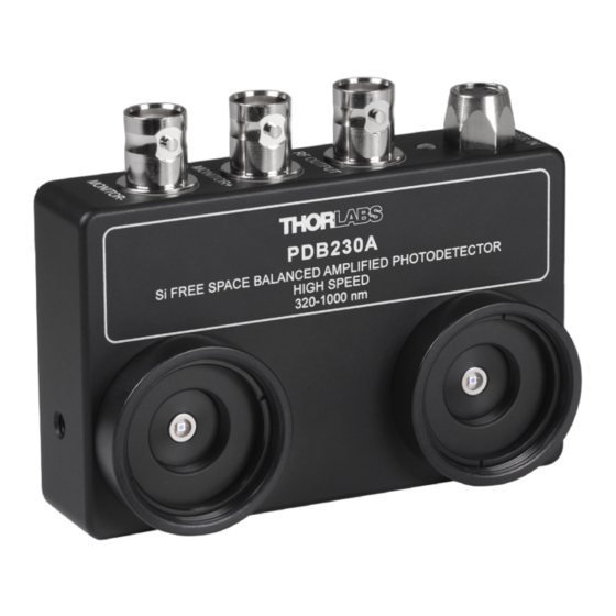
PDB2xx Series 3 Operating Instructions 3.1 Operating Elements PDB230A operating elements are identical in all products of the PDB2xx Series described in this manual. PDB230A Right Side of PDB230A: Page 4 MTN003813_D02... -
Page 9: Operating Principle
For this, Thorlabs offers a large variety of lenses and mounting accessories. The housing is compatible with any number of Thorlabs SM1- and SM05-threaded accessories, al- lowing for easy integration with external optics, filters, apertures, or fibers adapters as well as Thorlabs cage assembly accessories. -
Page 10: Electrical Output Ports
Attention The optical damage threshold is 20 mW. Exceeding this value will permanently damage the photodiodes! 3.4 Electrical Output Ports The Thorlabs PDB2xx Series has three BNC output connectors: · MONITOR + · MONITOR - · RF OUTPUT RF OUTPUT delivers an output voltage proportional to the difference between the photo cur- rents of the two photodiodes. -
Page 11: Mounting
This slim line housing has three tapped holes for convenient mount- ing to the optical setup. PDB210A, PDB201C and PDB220A2 can be purchased as imperial or metric versions (/M) with the tapped mounting holes 8/32 or M4, respectively. PDB230A and PDB230C feature tapped holes which are compatible for both imperial and metric threads. -
Page 12: Cmrr And Frequency Response
PDB2xx Series 3 Operating Instructions 3.7 CMRR and Frequency Response An important specification for balanced amplifiers is the Common Mode Rejection Ratio (CMRR) that reflects the ability to suppress common mode noise. In the setup described below, the Device under Test (DuT) - here a PDB2xx Series balanced detector - is tested for CMRR. -
Page 13: Recommendations
Performance Plots 3.8 Recommendations Thorlabs PDB2xx Series Balanced Amplified Photodetectors can eliminate noise sources to al- low precise measurements. The PDB2xx Series is designed for use in a dual beam setup: one optical path for measurement and one invariant reference path. If set up properly, the PDB2xx Series can reduce common mode noise for more than 35 dB over the specified frequency range. - Page 14 · Electrostatic coupling of electrical noise associated with ground loops will introduce electrical noise. In most cases an electrically isolated post (see Thorlabs parts TRE or TRE/M) will suppress electrical noise coupling. Always try to identify the electrical noise sources and in- crease the distance to the PDB2xx Series Balanced Detector.
-
Page 15: Maintenance And Service
When cleaning the windows of the photodetectors, please remember that is a sensitive optical device. Gently blow off any dust using compressed air and wipe gently with an optic tissue moistened with isopropanol or alcohol. Rev: 2.4, 16-Jul-2021 © 2021 Thorlabs Page 11... -
Page 16: Appendix
PDB2xx Series 5 Appendix 5 Appendix 5.1 Technical Data Model PDB220A2 PDB210A PDB210C Detector Detector Type UV Enhanced Si/PIN Si/PIN InGaAs/PIN Wavelength Range 190 to 1100 nm 320 to 1060 nm 800 to 1700 nm Max. Responsivity, typ. 0.5 A/W @ 960 nm 0.6 A/W @ 920 nm... - Page 17 ± 12 V @ 250 mA Included Power Supply (100/120/230 VAC, 50-60 Hz, Switchable) ) non-condensing All technical data are valid at 23 ± 5°C and 45 ± 15% rel. humidity (non condensing) Rev: 2.4, 16-Jul-2021 © 2021 Thorlabs Page 13...
-
Page 18: Technical Data Explained
PDB2xx Series 5 Appendix 5.2 Technical Data Explained Comments and explanations to the individual specifications  Typical max. responsivity is the peak responsivity of the photo diode. Transimpedance Gain [V/A] is the ratio of the output voltage to the photo current: RF,OUT RF,OUT ( ) l... -
Page 19: Performance Plots
5 Appendix PDB2xx Series 5.3 Performance Plots 5.3.1 PDB210A Performance Plots 5.3.2 PDB210C Performance Plots Rev: 2.4, 16-Jul-2021 © 2021 Thorlabs Page 15... -
Page 20: Pdb220A2 Performance Plots
PDB2xx Series 5 Appendix 5.3.3 PDB220A2 Performance Plots 5.3.4 PBD230A Performance Plots Page 16 MTN003813_D02... -
Page 21: Pbd230C Performance Plots
5 Appendix PDB2xx Series 5.3.5 PBD230C Performance Plots Rev: 2.4, 16-Jul-2021 © 2021 Thorlabs Page 17... -
Page 22: Dimensions
The threads for post mounting are metric (M4), imperial (8-32) or universal (M4 and 8-32) de- pending on the model as listed in the table below. Outer dimensions may vary slightly. Please have a look at the respective technical drawings on the Thorlabs website. Item# Threads for Post Mounting... -
Page 23: Certifications And Compliances
5 Appendix PDB2xx Series 5.5 Certifications and Compliances Rev: 2.4, 16-Jul-2021 © 2021 Thorlabs Page 19... -
Page 24: Safety
All rights reserved. This document may not be reproduced, transmitted or translated to another language, either as a whole or in parts, without the prior written permission of Thorlabs. Copy- right © Thorlabs 2021. All rights reserved. -
Page 25: Thorlabs Worldwide Contacts
EC, and are not dissembled or contaminated. Contact Thorlabs for more informa- tion. Waste treatment is your own responsibility. “End of life” units must be returned to Thorlabs or handed to a company specializing in waste recovery. Do not dispose of the unit in a litter bin or at a public waste disposal site. - Page 26 www.thorlabs.com...
Need help?
Do you have a question about the PDB210A and is the answer not in the manual?
Questions and answers