Table of Contents
Advertisement
Quick Links
Mainboard User's Manual
This publication, including all photographs, illustrations and
software, is protected under international copyright laws, with all
rights reserved. Neither this manual, nor any of the material
contained herein, may be reproduced without the express written
consent of the manufacturer.
The information in this document is subject to change without
notice. The manufacturer makes no representations or warranties
with respect to the contents hereof and specifically disclaims any
implied warranties of merchantability or fitness for any particular
purpose. Further, the manufacturer reserves the right to revise this
publication and to make changes from time to time in the content
hereof without obligation of the manufacturer to notify any person
of such revision or changes.
Trademarks
IBM, VGA, and PS/2 are registered trademarks of International
Business Machines.
Intel, Pentium, Pentium-II, Pentium-III, MMX, and Celeron are
registered trademarks of Intel Corporation.
Microsoft, MS-DOS and Windows NT/95/98/2000 are registered
trademarks of Microsoft Corporation.
Sound Blaster is a trademark of Creative Technology Ltd.
PC-cillin and ChipAwayVirus are trademarks of Trend Micro Inc.
AMI is a trademark of American Megatrends Inc.
A3D is a registered trademark of Aureal Inc.
SuperVoice is a registered trademark of Pacific Image
Communications Inc.
MediaRing Talk is a registered trademark of MediaRing Inc.
3Deep is a registered trademark of E-Color Inc.
Other names used in this publication may be trademarks and are
acknowledged.
Copyright © 2001
All Rights Reserved
M583 Series, V1.3B
A156X/April 2001
Advertisement
Table of Contents

Related Manuals for PCchips M583 Series


Summary of Contents for PCchips M583 Series
- Page 1 MediaRing Talk is a registered trademark of MediaRing Inc. 3Deep is a registered trademark of E-Color Inc. Other names used in this publication may be trademarks and are acknowledged. Copyright © 2001 All Rights Reserved M583 Series, V1.3B A156X/April 2001...
- Page 2 M583LMR Mainboard User’s Manual Federal Communications Commission (FCC) This equipment has been tested and found to comply with the limits for a Class B digital device, pursuant to Part 15 of the FCC Rules. These limits are designed to provide reasonable protection against harmful interference in a residential installation.
-
Page 3: Table Of Contents
M583LMR Mainboard User’s Manual Table of Contents Chapter 1: Introduction..............1 Key Features................2 Package Contents..............5 Static Electricity Precautions..........6 Pre-Installation Inspection............6 Chapter 2: Mainboard Installation..........7 Mainboard Components............8 I/O Ports..................9 Install A CPU................9 Install Memory..............11 Setting Jumper Switches............12 Install the Mainboard............14 Install the Extension Brackets..........16 Install Other Devices............17 Expansion Slots..............19 Chapter 3: BIOS Setup Utility............21... - Page 4 M583LMR Mainboard User’s Manual...
-
Page 5: Chapter 1: Introduction
1: Introduction Chapter 1 Introduction This mainboard supports all Socket 7 processors including newer designs which feature a 100 MHz system bus. The mainboard firmware supports CPU Plug and Play so that the system will automatically adopt the correct configuration for the Socket-7 processor that you install. -
Page 6: Key Features
M583LMR Mainboard User’s Manual Key Features The key features of this mainboard include: Socket-7 Processor Support Supports all recent socket-7 processors including the Intel P55C (Pentium MMX), the Cyrix/IBM 6x86L/6x86MX /MII, the AMD K6/K6-2/K6-III, IDT C6, and WinChip 2/2A CPUs ... - Page 7 1: Introduction Built-in Graphics System Onboard advanced 128-bit 2D/3D AGP Graphics Accelerator Supports Hardware Geometry Engine Shared SDRAM memory architecture allows a maximum of 32 MB main memory to act as frame buffer Supports high resolutions up to 1600x1200 and 32-bit color pipeline, up to 2048x2048 Texture size and Virtual screen up to 4096x4096 ...
- Page 8 M583LMR Mainboard User’s Manual One serial port with 16550-compatible fast UART One parallel port with ECP and EPP support Two USB ports Two PS/2 ports for keyboard and mouse One infrared port header for optional module Built-in Ethernet LAN ...
-
Page 9: Package Contents
1: Introduction Dimensions Flex-ATX form factor (22.9cm x 19cm) Package Contents Attention: This mainboard series includes four different models. They are M583LMR (LAN/Modem Ready), M583LR (LAN Ready), M583MR (Modem Ready) and M583 (without LAN & Modem). Please contact your local supplier for your purchase model. Each model will support different specification, list as below: Model Specification... -
Page 10: Static Electricity Precautions
M583LMR Mainboard User’s Manual Static Electricity Precautions Components on this mainboard can be damaged by static electricity. Take the following precautions when unpacking the mainboard and installing it in a system. 1. Keep the mainboard and other components in their original static-proof packaging until you are ready to install them. -
Page 11: Chapter 2: Mainboard Installation
2: Mainboard Installation Chapter 2 Mainboard Installation To install this mainboard in a system, follow the procedures in this chapter: Identify the mainboard components Install a CPU Install one or more system memory modules Verify that any jumpers or switches are set correctly ... -
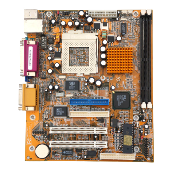
Page 12: Mainboard Components
M583LMR Mainboard User’s Manual Mainboard Components Use the diagram below to identify the major components on the mainboard. Note: Any jumpers on your mainboard that do not appear in this illustration are for testing only. -
Page 13: I/O Ports
2: Mainboard Installation I/O Ports The illustration below shows a side view of the built-in I/O ports on the mainboard. Install A CPU This mainboard has a Socket-7 which may be installed with any of the socket-7 processors including the Intel P55C (MMX) series, the Cyrix/IBM 6x86L/6x86MX/MII series, the AMD K6/K6-2/K- III series, the IDT C6/Winchip 2/2A series. - Page 14 M583LMR Mainboard User’s Manual The socket-7 processor installs into the ZIF (Zero Insertion Force) socket-7 on the mainboard. 1. Locate the Socket-7 and FAN1. Pull the locking lever out slightly from the socket and raise it to the upright position. Socket-7 Pin-1 Corner FAN1...
-
Page 15: Install Memory
2: Mainboard Installation Install Memory The mainboard has two DIMM sockets for system memory modules. You must install at least one memory module in order to use the mainboard. DIMM1 DIMM2 For this mainboard, you must use 168-pin, 3.3V unbuffered SDRAM memory modules. -
Page 16: Setting Jumper Switches
M583LMR Mainboard User’s Manual Setting Jumper Switches Jumpers are sets of pins which can be connected together with jumper caps. The jumper caps change the way the mainboard operates by changing the electronic circuits on the mainboard. If a jumper cap connects two pins, we say the pins are SHORT. If a jumper cap is removed from two pins, the pins are OPEN. - Page 17 2: Mainboard Installation Jumper JP4: Clear CMOS Memory Use this jumper to clear the contents of the CMOS memory. You may need to clear the CMOS memory if the settings in the Setup Utility are incorrect and prevent your mainboard from operating. To clear the CMOS memory, disconnect all the power cables from the mainboard and then move the jumper cap into the CLEAR setting for a few seconds.
-
Page 18: Install The Mainboard
M583LMR Mainboard User’s Manual Install the Mainboard Install the mainboard in a system chassis (case). The board is a flex-ATX size mainboard with a twin-tier of I/O ports. You can install this mainboard in any ATX case. Special micro-ATX cases are also available with a reduced number of expansion slot bays and a smaller power supply unit. - Page 19 2: Mainboard Installation Connect the case switches and indicator LEDs to the J7 switch and LED connector header. See the illustration below for a guide to the J7 connector pin assignments. Suspend LED Pins 19-20 HDD LED Speaker Pins 15-16 Pins 1-3-5-7 Keylock Reset Switch...
-
Page 20: Install The Extension Brackets
M583LMR Mainboard User’s Manual Install the Extension Brackets The extension brackets are used to connect features on the mainboard to external connectors that can be attached to the system chassis. Follow the steps below to install the extension brackets. Note: All the ribbon cables used on the extension brackets have a red stripe on the Pin-1 side of the cable. -
Page 21: Install Other Devices
2: Mainboard Installation Install Other Devices Install and connect any other devices in the system following the steps below. IDE2 IDE1 FDC1 Floppy Disk Drive The mainboard ships with a floppy disk drive cable that can support one or two drives. Drives can be 3.5” or 5.25” wide, with capacities of 360K, 720K, 1.2MB, 1.44MB, or 2.88MB. - Page 22 M583LMR Mainboard User’s Manual Internal Sound Connections If you have installed a CD-ROM drive or DVD-ROM drive, you can connect the drive audio cable to the onboard sound system. On the mainboard, locate the two 4-pin connectors CD1 and CD2. There are two kinds of connector because different brands of CD- ROM drive have different kinds of audio cable connectors.
-
Page 23: Expansion Slots
2: Mainboard Installation Infrared Port You can connect an infrared port to the mainboard. You can purchase this option from third-party vendors. 1. Locate the infrared port IR1 header on the mainboard. 2. If you are adding an infrared port, connect the ribbon cable from the port to the header and then secure the port to an appropriate place in your system chassis. - Page 24 M583LMR Mainboard User’s Manual 2. Remove the slot cover for the expansion slot from the system chassis. 3. Insert the expansion card edge connector into the slot and press it firmly down into it so that it is fully inserted. 4.
-
Page 25: Chapter 3: Bios Setup Utility
3: BIOS Setup Utility Chapter 3 BIOS Setup Utility Introduction The BIOS Setup Utility records settings and information about your computer such as the date and time, the kind of hardware installed, and various configuration settings. Your computer uses this information to initialize all the components when booting up and functions as the basis for coordination between system components. -
Page 26: Running The Setup Utility
M583LMR Mainboard User’s Manual Running the Setup Utility Each time your computer starts, before the operating system loads, a message appears on the screen that prompts you to “Hit <DEL> if you want to run SETUP”. When you see this message, press the Delete key and the Main menu page of the Setup Utility appears on your monitor. -
Page 27: Standard Cmos Setup Page
3: BIOS Setup Utility Standard CMOS Setup Page Use this page to set basic information such as the date and time, the IDE devices, and the diskette drives. If you press the F3 key, the system will automatically detect and configure the hard disks on the IDE channels. -
Page 28: Advanced Setup Page
M583LMR Mainboard User’s Manual Advanced Setup Page Use this page to set more advanced information about your system. Take some care with this page. Making changes can affect the operation of your computer. AMIBIOS SETUP – ADVANCED SETUP ©1999 American Megatrends, Inc. All Rights Reserved Trend ChipAway Virus Enabled Share Memory Size... - Page 29 3: BIOS Setup Utility Floppy Drive If you enable this item, your system will check all Seek floppy disk drives at start up. Disable this item unless you are using an old 360KB drive. PS/2 Mouse If this item is set to Enabled, the onboard PS/2 Support Mouse port will work.
-
Page 30: Power Management Setup Page
M583LMR Mainboard User’s Manual Power Management Setup Page This page sets some of the parameters for system power management operation. AMIBIOS SETUP – POWER MANAGEMENT SETUP ©1999 American Megatrends, Inc. All Rights Reserved Power Management/APM Disabled Standby Time Out Disabled Suspend Time Out Disabled Ring On Power On... - Page 31 3: BIOS Setup Utility LAN Card Power The system can be turned off with a software command. If you enable this item, the system can automatically resume if there is traffic on the network adapter. You must use an ATX power supply in order to use this feature.
-
Page 32: Pci / Plug And Play Setup Page
M583LMR Mainboard User’s Manual PCI / Plug and Play Setup Page This page sets some of the parameters for devices installed on the PCI bus and devices that use the system plug and play capability. AMIBIOS SETUP – PCI / PLUG AND PLAY SETUP ©1999 American Megatrends, Inc. -
Page 33: Load Optimal Settings
3: BIOS Setup Utility Load Optimal Settings If you select this item and press Enter a dialog box appears. If you press Y, and then Enter, the Setup Utility loads a set of fail-safe default values. These default values are not very demanding and they should allow your system to function with most kinds of hardware and memory chips. - Page 34 M583LMR Mainboard User’s Manual OnBoard Serial Use this item to enable or disable the onboard COM1 serial port, and to assign a port address Port OnBoard Ir Port Use this item to define the protocol for an infrared port if you have installed an optional IR port.
-
Page 35: Cpu Pnp Setup Page
3: BIOS Setup Utility CPU PnP Setup Page This page lets you manually configure the mainboard for the CPU. The system will automatically detect the kind of CPU that you have installed and make the appropriate adjustments to the items on this page. -
Page 36: Hardware Monitor Page
M583LMR Mainboard User’s Manual Hardware Monitor Page This page sets some of the parameters for the hardware monitoring function of this mainboard. AMIBIOS SETUP – HARDWARE Monitor ©1999 American Megatrends, Inc. All Rights Reserved --- Hardware Monitor --- System Temperature 30°C/86°F CPU Temperature 30°C/86°F... -
Page 37: Exit
3: BIOS Setup Utility Change or Remove the Password Highlight this item, press Enter and type in the current password. At the next dialog box, type in the new password, or just press Enter to disable password protection. Exit Highlight this item and press Enter to save the changes that you have made in the Setup Utility configuration and exit the program. - Page 38 M583LMR Mainboard User’s Manual...
-
Page 39: Chapter 4: Software & Applications
4: Software & Applications Chapter 4 Software & Applications Introduction The support software CD-ROM that is included in the mainboard package contains all the drivers and utility programs needed to properly run our products. Below you can find a brief description of each software program, and the location for your mainboard version. - Page 40 M583LMR Mainboard User’s Manual Note: The correct path name for each software driver is provided, where D: identifies the CD-ROM drive letter – modify if necessary. Bus Master IDE Driver The IDE Bus Master Drivers allow the system to properly manage the IDE channels on the mainboard.
-
Page 41: Auto-Installing Under Windows 98
4: Software & Applications BIOS Update Utility The BIOS Update utility allows you to update the BIOS file on the mainboard to a newer version. You can download the latest version of the BIOS setup available for your mainboard from the website. ... - Page 42 M583LMR Mainboard User’s Manual When you click on the Setup button the software installation program will run and you can select what kind of installation you want to do, as explained later in this section. The Browse CD button is the standard Windows command that allows you to examine the contents of the disc using the Windows 98 file browsing interface.
-
Page 43: Using The Pci Audio Software
4: Software & Applications 3. The support software will automatically install. Once any of the installation procedures start, software is automatically installed in sequence. You will need to follow the onscreen instructions, confirm commands and allow the computer to restart as few times as is needed to complete installing whatever software you selected to install. -
Page 44: The Four Speakers System
M583LMR Mainboard User’s Manual The Four Speakers System The onboard PCI Sound Pro audio system supports 2 wave channels (front/rear) known as the 4 speaker system. If you are running applications which use the DirectSound® 3D or A3D® audio interface, your system can simulate realistic 3D sound through a 4 speaker setup. - Page 45 4: Software & Applications avoid hardware conflicts, DO NOT enable this option when the Line-in/Rear jack is connected with a line-in device. While the 4 speakers mode is enabled, turn on/off the output of the front speakers and adjust the volume of the speakers so that the front/rear speakers have the same volume.
Need help?
Do you have a question about the M583 Series and is the answer not in the manual?
Questions and answers