Advertisement
Quick Links
Advertisement

Related Manuals for AMGO LR06


Summary of Contents for AMGO LR06
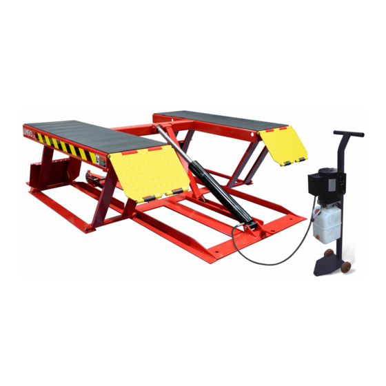
- Page 1 Original Portable Low-rised scissors lift Model:LR06...
-
Page 2: Table Of Contents
CONTENTS Product Features and Specifications ............1 Installation Requirement ................2 Step of Installation .................. 3 Exploded View ..................7 Operation Instructions ................13 Maintenance Schedule ................14 Trouble Shooting ................... 15 Lift disposal ..................15... -
Page 3: Product Features And Specifications
I. PRODUCT FEATURES AND SPECIFICATIONS (See Fig.1) PORTABLE LOW-RISED MODEL LR06 · Self-locking safety device: 3 stage safety lock, mechanical lock, automatic release. · Portable unit is easy to move with the power unit stand · High speed: From 0-23 5/8” just 21 seconds ·... -
Page 4: Installation Requirement
II. INSTALLATION REQUIREMENT A. Tools requirement Screw Set Grease gun Pliers Socket Head Wrench (8″) Wrench sets # # # # :(13 、15 、17 、19 Fig.2 B. Power requirement The electrical source must be 2.2KW minimum. The source cable size must be 2.5mm²... -
Page 5: Step Of Installation
III. STEPS OF INSTALLATION A. Check the parts before assembly, make sure all the parts are completed. Packaged lift, Parts box, Power Unit and Power Unit Stand. Move aside the parts, Open the outer packing and check the parts according to the shipment parts list (See Fig. - Page 6 Check the parts of the parts bag according to the parts bag list (See Fig. 5) Fig. 5 B. Install hydraulic power unit (See Fig. 6) Fig. 6...
- Page 7 C. Install fitting to power unit, and then connecting oil hose (See Fig.7). Fig. 7...
- Page 8 D. Install electrical system Connect the power source on the data plate of power unit. Note: 1. For the safety of operators, the power wiring must contact the floor well. 2. Pay attention to the direction of rotations when using three phrases motors.
-
Page 9: Exploded View
IV. EXPLODED VIEW MODEL LR06 Fig. 9 Rollers Fig. 10... - Page 10 PARTS LIST FOR MODEL LR06 Note Item Part# Description QTY. 11630001 Platform 10206019 Snap ring 11630003 Pin for drive-thru ramp 11630004 Drive-thru ramp 10209010 Snap Ring 11620043 Pin for roller of drive-in ramp 10620063 Roller of drive-pin ramp 11630005 Connecting pin for cylinder...
- Page 11 Cylinder Fig. 11 Item Part No. Description QTY. Note 11630029 Bore Weldment 11630026 Piston Rod 10201034 Bleeding Plug 11630030 Head cap 10209078 Dust ring 10620058 O - Ring 10620049 O - Ring 11630028 Piston 10206069 O-Ring 6-10 10630027 O-Ring 6-11 10620054 Y-Ring 6-12...
- Page 12 Manual Power Unit (071104) Fig. 12...
- Page 13 85090167 Magnet 81400290 Filter 81400413 Motor 10420070 Push Button 41030055 AC Contactor 81400287 Cover of Motor terminal box 71111174 AMGO label 81400560 Throttle valve 81400266 Relief Valve 81400284 Plug 10720118 Elastic latch 81400451 Release valve handle 10209020 Black plastic ball...
- Page 14 Illustration of hydraulic valve for power unit Protective ring Relief valve Oil return port Release valve Handle for release valve Throttle valve Oil Outlet Check valve Fig. 13...
-
Page 15: Operation Instructions
V. OPERATION INSTRUCTIONS 1. Install the oil hose between oil cylinder and power unit, connect well the power supply wire. The machine can be ready to use. 2. The roller must be disengage when lifting vehicle . To raise and lock the (See Fig.16) lift: Press the button up till the lift is raised to the required height and the locks are in engaged... -
Page 16: Maintenance Schedule
5. There are four fixed holes in the machine, can fix the machine on ground by 3/4 X 4 3/4” anchor bolts (See Fig.18) Fig.18 VI. MAINTENANCE SCHEDULE Monthly: 1. Lubricate all moving parts with lubricant. 2. Check all connectors, bolts and pins to insure proper mounting. 3. -
Page 17: Trouble Shooting
VII. TROUBLE SHOOTING TROUBLE CAUSE REMEDY 1. Start Button does not work 1. Replace start button 2. Wiring connections are not in good 2. Repair all wiring connections Motor does not condition 3. Motor burned out 3. Repair or replace motor 4. - Page 18 Manual Part No. : 72106302 Revision Date: : 2020/08...
Need help?
Do you have a question about the LR06 and is the answer not in the manual?
Questions and answers