Table of Contents
Advertisement
Available languages
Available languages
Quick Links
Advertisement
Table of Contents

Related Manuals for aerauliqa WHS Series


Summary of Contents for aerauliqa WHS Series
- Page 1 Manuale Specifico Specific Manual...
-
Page 2: Table Of Contents
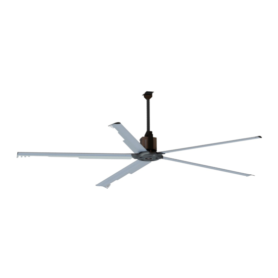
SERIE WHS Ventilatori da soffitto ad alte prestazioni (HVLS) INDICE 1. AVVERTENZE GENERALI 2. AVVERTENZE PARTICOLARI 3. TIPOLOGIA 4. CARATTERISTICHE PRINCIPALI 5. DATI 6. DIMENSIONI E DISTANZE 7. COMPONENTI 8. INSTALLAZIONE 9. SCHEMI COLLEGAMENTO ELETTRICO 9.1 CTRL-A (accessorio a richiesta) 9.2 CTRL-HS (accessorio a richiesta) 9.3 COMANDO CON POTENZIOMETRO ESTERNO (non fornito) 10. -
Page 3: Caratteristiche Principali
4. CARATTERISTICHE PRINCIPALI • Nessun ingranaggio, quindi silenziosità • Motore brushless 380-440 Vac, 3ph, 50/60Hz, IP55 • Nessuna manutenzione ordinaria • Temperatura max +50°C • Vari livelli di sicurezza • Regolabile • Connessioni elettriche semplificate • Adatto all’utilizzo in continuo, S1 • Struttura resistente e robusta • Sistema elettronico integrato • Pale estruse in alluminio 5. -
Page 4: Installazione
8. INSTALLAZIONE • Scegliere la posizione di installazione del ventilatore tenendo conto delle seguenti considerazioni: - la distanza minima tra il pavimento e il punto inferiore del ventilatore deve essere di 2,7m. - la minima distanza tra le pale e la parete o un qualsiasi altro ostacolo varia in base al modello scelto (§6 - C). - evitare l’installazione direttamente sotto una fonte di luce per prevenire un effetto stroboscopico causato dalla rotazione della girante. - Page 5 • Rimuovere corpo principale (1) le tre staffe di appoggio per il trasporto, togliendo le relative viti, rondelle e dadi. • Far fuoriuscire lateralmente la fune (16) del set di sicurezza, agganciando i moschettoni (19) ai golfari presenti sul motore, verificandone il corretto serraggio.
- Page 6 • Collegare cavi Ø3mm con tensionatore occhielli (21) supporto motore tramite i moschettoni da 5mm (22) e stabilizzare il ventilatore; fissare il capo libero dei cavi al soffitto e serrare con i morsetti (23). La viteria di fissaggio al soffitto/trave non è fornita in dotazione.
-
Page 7: Schemi Collegamento Elettrico
9. SCHEMI COLLEGAMENTO ELETTRICO • A ssicurarsi che la macchina non sia alimentata durante ogni operazione di installazione, manutenzione o servizio! • L ’installazione, i collegamenti elettrici e la manutenzione della macchina devono essere fatte da un installatore autorizzato e in accordo con le regole locali. -
Page 8: Comando Con Potenziometro Esterno (Non Fornito)
9.3 COMANDO CON POTENZIOMETRO ESTERNO (non fornito) YELLOW - GREEN BROWN 4-core power cable 3 ph. POWER BLACK 3 ph. SUPPLY ALIMENTAZIONE GREY YELLOW - GREEN BROWN BROWN 4-core power cable 3 ph. EXTERNAL POWER YELLOW POTENTIOMETER BLACK SUPPLY ≥10kΩ GREEN (NOT SUPPLIED) GREY... -
Page 9: Codici Di Allarme/Stato Del Led/Risoluzione Problemi
11.3 Codici di allarme/Stato del LED/Risoluzione Problemi VALORE VALORE DESCRIZIONE ALLARME ALLARME ALLARME RISOLUZIONE DEI PROBLEMI POSSIBILI CAUSE Nessun errore Errore di memoria – parametri motore persi Contattare il produttore/supporto tecnico. Corto circuito – elettronica di potenza danneggiata Scheda danneggiata – sostituire la scheda. Controllare gli avvolgimenti del motore. -
Page 10: Dichiarazione Di Conformità E Incorporazione
12. DICHIARAZIONE DI CONFORMITA’ E INCORPORAZIONE DICHIARAZIONE UE DI CONFORMITA’/INCORPORAZIONE Costruttore: AERAULIQA SRL Via Mario Calderara 39/41 - 25018 Montichiari (BS) - ITALY DICHIARAZIONE UE DI CONFORMITA’ DICHIARAZIONE DI INCORPORAZIONE In accordo alla Direttiva Macchine 2006/42/EC. Dichiariamo qui di seguito che I prodotti della gamma:... - Page 11 WHS RANGE Ceiling High Volume Low Speed Fan (HVLS) INDEX GENERAL INFORMATION 2. PRECUTIONS 3. TYPE 4. MAIN FEATURES 5. DATA 6. DIMENSIONS AND CLEARANCES 7. COMPONENTS 8. INSTALLATION 9. WIRING DIAGRAM 9.1 CTRL-A (accessory on request) 9.2 CTRL-HS (accessory on request) 9.3 CONTROL WITH EXTERNAL POTENTIOMETER (not supplied) 10.
- Page 12 4. MAIN FEATURES • Gearless for silent operation • Brushless motor 380-440Vac, 3ph, 50/60Hz, IP55 • Maintenance-free • Max temperature +50°C • Key Safety features • Speed controllable • Simplified electrical wiring connection • Suitable for S1 continuous service • Strong and robust design and manufacturing • Embedded electronic system • Extruded aluminium blades 5.
- Page 13 8. INSTALLATION • Decide on the position the fan is to be sited keeping in consideration as follows: - the minimum distance from the floor to the lowest point of the fan is 2.7m. - the minimum distance from the fan blade to the side wall of similar obstruction depends on the fan model (§ 6 - C). - avoid mounting the fan directly below lights to prevent any strobe effect caused by the moving blades.
- Page 14 • Remove three transport feet from the main body (1) by unscrewing the bolts, washers and locknuts. • Let out the safety wire (16) laterally, hooking the snap-hooks (19) to the eyebolts on the motor, verifying correct tightening. Staffe di appoggio per il trasporto in imballo transport foot Fig.
- Page 15 • Connect Ø3mm stabilizing wires with turnbuckle (21) to the motor support using the 5mm snap-hooks (22) to the motor support holes. Securely fix the other end of the stabilizing wires to the ceiling using the clamps (23). Fixing screws for the ceiling/ beam are not supplied.
- Page 16 9. WIRING DIAGRAM • M ake sure that the mains supply to the unit is disconnected before performing any installation, service, maintance or electrical work! • T he installation and service of the unit and complete ventilation system must be performed by an authorized installer and in accordance with local rules and regulations.
- Page 17 9.3 CONTROL WITH EXTERNAL POTENTIOMETER (not supplied) YELLOW - GREEN BROWN 4-core power cable 3 ph. POWER BLACK 3 ph. SUPPLY POWER GREY SUPPLY YELLOW - GREEN BROWN BROWN 4-core power cable 3 ph. EXTERNAL POWER YELLOW POTENTIOMETER BLACK SUPPLY ≥10kΩ...
- Page 18 11.3 Alarm codes/LED status/Troubleshooting ALARM 1 ALARM 2 ALARM DESCRIPTION TROUBLESHOOTING VALUE VALUE POSSIBLE CAUSE No error Memory error – motor parameters lost Contact manufacturer/technical support Short circuit – electronics power Board damaged – replace board module damaged Check motor windings. Motor synchronization lost –...
- Page 19 UE DECLARATION OF INCORPORATION In accordance with the Machinery Directive 2006/42/EC. We herewith declare that the following range: We herewith declare that the following range: WHS series ceiling fans WHS series ceiling fans MODELS: WHS400, WHS500, WHS600 MODELS: WHS400, WHS500, WHS600...
- Page 20 Sede operativa/Warehouse-Offices: via Mario Calderara 39/41, 25018 Montichiari (Bs) - Sede legale/Registered office: via Mario Calderara 39/41, 25018 Montichiari (Bs) C.F. e P.IVA/VAT 03369930981 - REA BS-528635 - Tel: +39 030 674681 - Fax: +39 030 6872149 - www.aerauliqa.it - www.aerauliqa.com - info@aerauliqa.it Aerauliqa S.r.l.
Need help?
Do you have a question about the WHS Series and is the answer not in the manual?
Questions and answers