
Subscribe to Our Youtube Channel
Related Manuals for Beckhoff KL9540


Summary of Contents for Beckhoff KL9540
- Page 1 Documentation | EN KL9540, KL9540-0010 and KL9550 Surge Filter Terminals 2020-07-21 | Version: 3.0.1...
-
Page 3: Table Of Contents
KL9540-0000 - connection ...................... 19 KL9540-0010 - connection ...................... 20 KL9550-0000 - connection ...................... 21 KL9540-0000, KL9550-0000 - application example ................ 22 KL9540-0010, KL9550-0000 - application example ................ 23 Installation instructions for enhanced mechanical load capacity ............. 24 ATEX - Special conditions (standard temperature range) ............... 25 3.10 ATEX - Special conditions (extended temperature range) .............. 26... - Page 4 Table of contents Version: 3.0.1 KL9540, KL9540-0010 and KL9550...
-
Page 5: Foreword
EP1590927, EP1789857, EP1456722, EP2137893, DE102015105702 with corresponding applications or registrations in various other countries. ® EtherCAT is registered trademark and patented technology, licensed by Beckhoff Automation GmbH, Germany. Copyright © Beckhoff Automation GmbH & Co. KG, Germany. The reproduction, distribution and utilization of this document as well as the communication of its contents to others without express authorization are prohibited. -
Page 6: Safety Instructions
All the components are supplied in particular hardware and software configurations appropriate for the application. Modifications to hardware or software configurations other than those described in the documentation are not permitted, and nullify the liability of Beckhoff Automation GmbH & Co. KG. Personnel qualification This description is only intended for trained specialists in control, automation and drive engineering who are familiar with the applicable national standards. -
Page 7: Documentation Issue Status
• Technical data updated 3.0.0 • Migration 2.1.0 • Technical data updated • ATEX notes added • KL9540-0010 updated 2.0.0 • Permitted ambient temperature range extended • KL9540-0010 added First public issue (describes KL9540-0000 and KL9550-0000) KL9540, KL9540-0010 and KL9550 Version: 3.0.1... -
Page 8: Product Overview
• KL9540-0000 / KS9540-0000 [} 9]: Surge filter terminals for field supply • KL9540-0010 / KS9540-0010: [} 10] Surge filter terminals for field supply of analog Bus Terminals • KL9550-0000 / KS9550-0000 [} 11]: Surge filter terminals for field supply and K-Bus supply... -
Page 9: Kl9540-0000 - Introduction
Fig. 1: KL9540 Surge filter terminals for field supply The KL9540-0000 surge filter terminal contains an overvoltage filter for the field supply. The filter protects the components from line-bound surge voltages that can occur due to high-energy disturbance variables such as switching surges at inductive consumers or lightning strikes at the supply lines. -
Page 10: Kl9540-0010 - Introduction
The use of such overvoltage filters is stipulated by the ship classification organizations in shipbuilding and on/offshore applications in which GL certification is required. The KL9540-0010 is intended in particular for the protection of analog terminals; the standard variant KL9540 for digital terminals. -
Page 11: Kl9550-0000 - Introduction
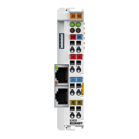
LED displays Meaning Power system (green) K-Bus supply voltage present Power field (green) Field supply voltage present KL9540, KL9540-0010 and KL9550 Version: 3.0.1... -
Page 12: Technical Data
EN 60068-2-6/EN 60068-2-27, see also Installation instructions [} 24] for terminals with enhanced mechanical load capacity EMC immunity / emission conforms to EN 61000-6-2 / EN 61000-6-4 Protection class IP20 Installation position variable Approval CE, cULus, ATEX, GL CE, cULus, GL Version: 3.0.1 KL9540, KL9540-0010 and KL9550... -
Page 13: Mounting And Wiring
To mount the mounting rails with a height of 7.5 mm under the terminals and couplers, you should use flat mounting connections (e.g. countersunk screws or blind rivets). KL9540, KL9540-0010 and KL9550 Version: 3.0.1... -
Page 14: Fig. 5 Disassembling Of Terminal
PE power contact The power contact labeled PE can be used as a protective earth. For safety reasons this contact mates first when plugging together, and can ground short-circuit currents of up to 125 A. Version: 3.0.1 KL9540, KL9540-0010 and KL9550... -
Page 15: Connection System
• The terminals of KSxxxx and ESxxxx series feature a pluggable connection level and enable steady wiring while replacing. • The High Density Terminals (HD Terminals) include electronics and connection level in a single enclosure and have advanced packaging density. KL9540, KL9540-0010 and KL9550 Version: 3.0.1... -
Page 16: Fig. 7 Standard Wiring
12 mm Bus Terminals. Massive conductors and conductors with a wire end sleeve can be inserted directly into the spring loaded terminal point without tools. Version: 3.0.1 KL9540, KL9540-0010 and KL9550... -
Page 17: Fig. 10 Mounting A Cable On A Terminal Connection
The cables are released, as usual, using the contact release with the aid of a screwdriver. See the following table for the suitable wire size width. KL9540, KL9540-0010 and KL9550 Version: 3.0.1... - Page 18 0.25 ... 1.5 mm Wire size width (ultrasonically “bonded" conductors) only 1.5 mm (see notice [} 17]!) Wire stripping length 8 ... 9 mm Shielding Shielding Analog sensors and actors should always be connected with shielded, twisted paired wires. Version: 3.0.1 KL9540, KL9540-0010 and KL9550...
-
Page 19: Kl9540-0000 - Connection
Field supply feed for the power contacts (internally connected to terminal point 7) 0 V Field supply feed for the power contacts (internally connected to terminal point 3) PE connection (internally connected to terminal point 8) PE connection (internally connected to terminal point 4) KL9540, KL9540-0010 and KL9550 Version: 3.0.1... -
Page 20: Kl9540-0010 - Connection
Field supply feed for the power contacts +24 V output internally connected to positive power contact 0 V input Field supply feed for the power contacts 0 V output internally connected to negative power contact not used not used Version: 3.0.1 KL9540, KL9540-0010 and KL9550... -
Page 21: Kl9550-0000 - Connection
Field supply feed for the power contacts (internally connected to terminal point 7) 0 V Field supply feed for the power contacts (internally connected to terminal point 3) System power +24 V in 4 System supply feed +0 V in system power System supply feed KL9540, KL9540-0010 and KL9550 Version: 3.0.1... -
Page 22: Kl9540-0000, Kl9550-0000 - Application Example
: K-Bus supply) ◦ the field voltage (U : power contacts, potential group 1) • a KL9540-0000 Surge Filter Terminal in conjunction with the KL9190 power feed terminal for power supply ◦ the field voltage (U : power contacts, potential group 2) Fig. 14: Application example KL9540, KL9550... -
Page 23: Kl9540-0010, Kl9550-0000 - Application Example
: K-Bus power supply) ◦ the field voltage for the digital terminals (U : power contacts, potential group 1) • a KL9540-0010 Surge Filter Terminal for power supply ◦ the field voltage for the analog terminals (U : power contacts, potential group 2) Fig. 15: KL9540-0010, KL9550-0000 - application example... -
Page 24: Installation Instructions For Enhanced Mechanical Load Capacity
• Use countersunk head screws to fasten the mounting rail • The free length between the strain relief and the wire connection should be kept as short as possible. A distance of approx. 10 cm should be maintained to the cable duct. Version: 3.0.1 KL9540, KL9540-0010 and KL9550... -
Page 25: Atex - Special Conditions (Standard Temperature Range)
80°C at the wire branching points, then cables must be selected whose tempera- ture data correspond to the actual measured temperature values! • Observe the permissible ambient temperature range of 0 to 55°C for the use of Beckhoff fieldbus compo- nents standard temperature range in potentially explosive areas! •... -
Page 26: Atex - Special Conditions (Extended Temperature Range)
80°C at the wire branching points, then cables must be selected whose tempera- ture data correspond to the actual measured temperature values! • Observe the permissible ambient temperature range of -25 to 60°C for the use of Beckhoff fieldbus com- ponents with extended temperature range (ET) in potentially explosive areas! •... -
Page 27: Continuative Documentation About Explosion Protection
Explosion protection for terminal systems Pay also attention to the continuative documentation Notes on the use of the Beckhoff terminal systems in hazardous areas according to ATEX and IECEx that is available for download on the Beckhoff homepage https:\\www.beckhoff.com! KL9540, KL9540-0010 and KL9550 Version: 3.0.1... -
Page 28: Appendix
Beckhoff's branch offices and representatives Please contact your Beckhoff branch office or representative for local support and service on Beckhoff products! The addresses of Beckhoff's branch offices and representatives round the world can be found on her internet pages: http://www.beckhoff.com You will also find further documentation for Beckhoff components there. - Page 29 Mounting a cable on a terminal connection ................. Fig. 11 KL9540 connection ........................Fig. 12 KL9540-0010 connection......................Fig. 13 KL9550 ............................Fig. 14 Application example KL9540, KL9550..................Fig. 15 KL9540-0010, KL9550-0000 - application example..............KL9540, KL9540-0010 and KL9550 Version: 3.0.1...
- Page 31 Beckhoff Automation GmbH & Co. KG Hülshorstweg 20 33415 Verl Germany Phone: +49 5246 9630 info@beckhoff.com www.beckhoff.com...
Need help?
Do you have a question about the KL9540 and is the answer not in the manual?
Questions and answers