Table of Contents
Advertisement
Quick Links
Instruction Manual
D103565X012
Fisher
SS-264 Rotary Control Ball Valve
™
Contents
. . . . . . . . . . . . . . . . . . . . . . . . . . . . . . . . .
. . . . . . . . . . . . . . . . . . . . . . . . . . . . .
. . . . . . . . . . . . . . . . . . . . . . . . . . . . . . . . .
. . . . . . . . . . . . . . . . . . . . . . . . . . . . . . .
. . . . . . . . . . . . . . . . . . . . . . . . .
. . . . . . . . . . . . . . . . . . . . . . . . .
. . . . . . . . . . . . . . . . . . . . . . . . . . . . . . . . . . . .
. . . . . . . . . . . . . . . . . . . . . . . . . . . .
. . . . . . . . . . . . . . . . . . . . . . . . . . . . . . . . . .
. . . . . . . . . . . . . . . . . . . . . . . . .
. . . . . . . . . . . . . . . . . . . . . . . . . . . . .
. . . . . . . . . . . . . . . . . . . . . . . . . . . .
™
. . . . . . . . . . . . . . . . . . . . . . . . . . . . . . . .
. . . . . . . . . . . . . . . . . . . . . . . . . . . . . . . . . . . . .
. . . . . . . . . . . . . . . . . . . . . . . . . . . . . . . . .
Introduction
Scope of Manual
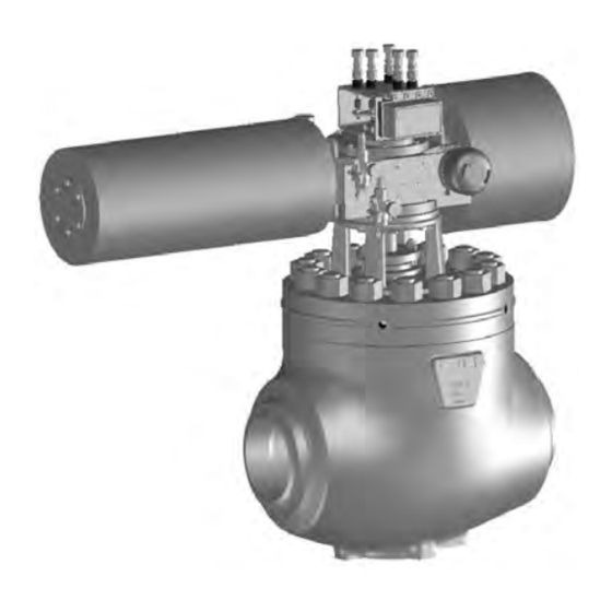
This instruction manual provides installation, operation, maintenance, and parts information for the Fisher SS-264
rotary control valve (see figure 1). It also outlines the assembly and testing procedures for the CL1725 SS-264 rotary
ball valve designed for use with the Bettis NG4020-SR3 rotary actuator.
The SS-264 valve is the passive residual heat removal valve for use in third generation PWR Nuclear Generating
Stations. The valve body has NPS 14 (AP1000, CAP1000) or NPS 16 (CAP1400) butt weld ends with a cammed ball
operating against a one-piece metal seal.
Features include the following:
D Cammed, segmented ball with hard faced seat band manufactured from forged bar.
D Fisher involute spline connection for ball/shaft and a keyed connection which is used for the Bettis actuator
connection.
D Tight tolerances and heavily loaded ball/seal interface.
www.Fisher.com
. . . . . . . . . . . . . . . . . . . . . . . .
. . . . . . . . . . . . . . . .
. . . . . . . . . . . . . . . . . . . . .
. . . . . . . . . . . . . . .
. . . . . . . . . . . . . . . . . .
Figure 1. Fisher SS-264 Valve with Bettis
NG4020-SR3 Actuator and 3610J Positioner
1
1
2
2
2
3
3
5
7
8
8
11
11
18
18
24
25
30
30
32
09AA03200
SS-264 Valve
September 2021
™
Advertisement
Table of Contents

Related Manuals for Emerson Fisher SS-264


Summary of Contents for Emerson Fisher SS-264
-
Page 1: Table Of Contents
Introduction Scope of Manual This instruction manual provides installation, operation, maintenance, and parts information for the Fisher SS-264 rotary control valve (see figure 1). It also outlines the assembly and testing procedures for the CL1725 SS-264 rotary ball valve designed for use with the Bettis NG4020-SR3 rotary actuator. -
Page 2: Description
2. Exceeding pressure drop limits will begin to yield the metal seat ring and can cause deformation which may lead to excessive leakage though the valve seat. D Emerson Automation Solutions designed liveloaded packing with positive stop screws controlling Belleville spring deflection. -
Page 3: Principle Of Operation
Instruction Manual SS-264 Valve D103565X012 September 2021 Principle of Operation The ball and machined body combine to create smooth transitioning flow geometry which enables efficient flow through the valve. The drive shaft and follower shaft center the ball in the flow stream to minimize dynamic torque and permit easy ball rotation. - Page 4 To avoid possible personal injury and because some valve/trim material combinations are limited in their pressure drop and temperature ranges, do not apply any other conditions to the valve without first contacting your Emerson sales office. WARNING The valve drive shaft is not necessarily grounded to the pipeline when installed.
-
Page 5: Lifting Guidelines
Instruction Manual SS-264 Valve D103565X012 September 2021 Lifting Guidelines Figure 2. Lifting Guidelines X0420 X0397 X0398 X0399... - Page 6 Instruction Manual SS-264 Valve September 2021 D103565X012 Figure 3. Lifting Guidelines (continued) CAPSCREW ⅝-11UNC x 1.5 (NOT PROVIDED) LIFTING PLATE EYE BOLT ½-13UNC x 1.5 (NOT PROVIDED) CAUTION Care must be taken when lifting the valve/actuator assembly to ensure the accessories and tubing are not damaged in the process.
-
Page 7: Maintenance
Instruction Manual SS-264 Valve D103565X012 September 2021 To lift the actuator, choke two straps, one around the spring barrel and one around the air cylinder, and connect to an adjustable chain leveler. The chain leveler ensures the actuator and bonnet mating surfaces are parallel prior to removal or installation. -
Page 8: Packing Maintenance
Instruction Manual SS-264 Valve September 2021 D103565X012 D Use bypass valves or completely shut off the process to isolate the valve from process pressure. Relieve process pressure from both sides of the valve. Drain the process media from both sides of the valve. D Vent the power actuator loading pressure and relieve any actuator spring precompression. - Page 9 Instruction Manual SS-264 Valve D103565X012 September 2021 4. Use packing removal tools to pull the packing set (key 11) out of the bonnet (key 7). 5. Carefully clean the drive shaft (key 8) and packing box bore of the bonnet (key 5). Using a flashlight, look into the packing box bore and ensure all packing and residue are cleaned out.
- Page 10 Instruction Manual SS-264 Valve September 2021 D103565X012 13. If the stop screws (key 22 and 24) were not adjusted during disassembly, then check the Gap A and Gap B clearance using the gap gage and adjust if necessary following Section Stop Screw Gap Settings steps 3 and 4; if adjustments are not necessary, then proceed to Section Stop Screw Gap Settings step 5.
-
Page 11: Packing Load Adjustment
Instruction Manual SS-264 Valve D103565X012 September 2021 Packing Adjustment The following instructions describe how to set the correct stop screw gaps A and B for proper packing load. Gap A is the nominal packing load and should be used under normal circumstances. Gap B is the maximum packing load and should not be exceeded. - Page 12 Instruction Manual SS-264 Valve September 2021 D103565X012 4. Loosen and remove the body/bonnet nuts (key 117). 5. Using a safe lifting method, lift the bonnet (key 18) vertically off of the valve body (key 12); make sure the ball/shaft assembly (key 8) does not lift with the bonnet. CAUTION Ensure the bonnet flange remains level and parallel to body (key 12) mounting face.
- Page 13 3. Compare the thrust washer thickness to dimension A, as calculated in table 3, to the measured value. If the thickness differs +0.64 mm (+0.025 in), then contact your Emerson sales office to order a replacement Table 3. Thrust Bearing Calculation Table...
- Page 14 Instruction Manual SS-264 Valve September 2021 D103565X012 Figure 6. Thrust Washer Thickness Feature Assembly Figure 7. Seal Ring Masking MASKING ADHESIVE MASKING 1. Inspect parts, ensuring no rust, corrosion, or foreign material is present and that bearing, guide, and sealing surfaces do not have nicks or scratches.
- Page 15 Instruction Manual SS-264 Valve D103565X012 September 2021 6. Tighten cap screws (key 27) into the anchor ring (key 12B) tapped holes, using a multiple pass, cross pattern tightening procedure increasing the bolt torque at each pass until all the bolts are at the initial torque value of 45 N•m (33 ft•lbf) and a final torque value of 92 N•m (68 ft•lbf).
- Page 16 (key 28) must be ordered. All four of the components are a matched set and ensure proper vertical alignment of the ball with the seal. Contact your Emerson sales office for assistance with procuring a new special thrust washer. Use section Thrust Washer Dimension Check Instructions above.
- Page 17 Instruction Manual SS-264 Valve D103565X012 September 2021 Figure 9. Lower Thrust Washer and Ball Belleville Spring Installation Figure 10. Body/Bonnet Bolting Sequence...
-
Page 18: Troubleshooting
(key 25), and special thrust washer (key 28) for excessive wear or scratches. Other Consult your Emerson sales office. Actuator Mounting The open and closed travel stops of the actuator may require adjustment if the bonnettobody or bonnet-to-actuator joint is loosened. - Page 19 Instruction Manual SS-264 Valve D103565X012 September 2021 Figure 11. Actuator/Bonnet Bolting Sequence Determination of Ball Closed and Open Position The purpose of the following procedure is to establish the ‘closed’ and ‘open’ position for the ball/shaft assembly. Refer to figure 12. When the valve assembly is put together, the exact position of the ball relative to the seal is not known.
- Page 20 Refer to the beginning of this section for more background information on this procedure. If you have any questions, contact your Emerson sales office for assistance. CAUTION The following step, if done incorrectly, could severely damage the seal or ball significantly and/or cause undue stress on the shaft assembly causing damage.
- Page 21 Do not fill the actuator cylinder too quickly as the fast stroking speed could alter the zero positioning of the valve. Note If the process is continued until the regulator pressure reaches 48 psig and the step change has still not been reached, contact your Emerson sales office. Travel Stop Adjustments CAUTION Ensure all the step of the previous section have been followed before adjusting the travel stops.
- Page 22 Instruction Manual SS-264 Valve September 2021 D103565X012 Figure 12. Ball Angle and Travel Stop Reference SEAL RING BALL NEGATIVE (-) BALL ANGLE FLOW TOP VIEW POSITIVE (+) BALL ANGLE BALL RANGE OF MOTION CLOSED TRAVEL STOP (FRONT VIEW) ¼ TURN = 0.3 DEG BALL ROTATION 1 TURN = 1.2 DEG BALL ROTATION 8.
- Page 23 5. While holding the travel stop stationary, securely tighten the “closed” travel stop lock nut using a 1-13/16” wrench. Torque to 136 N•m (100 ft•lbf). 6. Recheck leakage per steps a through c. Contact your Emerson sales office if Class V cannot be achieved. Note Do NOT lap the ball and seal by cycling between each increment in step.
-
Page 24: Actuator Mounting Instructions
26 and 30 psig. If Class V shutoff is achieved with closing ”ramp-in” and opening ”jump” and the pressure is between 22-35 psig, then this is acceptable. See table 6 in the Periodic FlowScanner Testing section. For more information contact your Emerson sales office. Actuator Mounting Instructions Fisher 2625NS and Solenoid Mountings Refer to figure 15 for this accessory mounting section. -
Page 25: Periodic Flowscanner Testing
Instruction Manual SS-264 Valve D103565X012 September 2021 Note M6 screws in steps 2 and 4 are tightened in torque units of inch•lbf and NOT ft•lbf, take care not to over-tighten. 2. Apply Loctite 242 (key 77) to M6 x 12 socket head cap screw and attach the namur disc to the actuator, tightening to 10.2 N•m (90 in•lbf) with a 4 mm Allen wrench. - Page 26 Refer to the Component Part Qualification Report for verification of the weak-link torque limits: 5,200 N m (46,800 • lbf). This torque limit should not be exceeded or damage to the valve is likely to occur. Contact your Emerson sales office for assistance in performing the FlowScanner testing. Figure 14. Travel Stop SEATING 'RAMP-IN' OR...
- Page 27 Instruction Manual SS-264 Valve D103565X012 September 2021 Figure 15. Fisher 2625NS/Solenoid Mounting SCREW, CAP, HEX SOCKET (2) M6 X 1 X 20 MAGNET (4) NUT, HEX (4) 7/16-20 WASHER STAR (4) 7/16 WASHER PLAIN (4) 7/16 TRIP ARM (4) 7/16 WASHER STAR (4) 7/16 WASHER PLAIN (4) 7/16 POINTER...
- Page 28 Instruction Manual SS-264 Valve September 2021 D103565X012 Figure 16. Fisher 546 I/P Transducer/67CFSR Mounting and 3610J Positioner/GO Switch Mounting GO SWITCH (5) MOUNTING BRACKET ASSEMBLY ADAPTOR, SWITCH (5) SCREW, CAP, HEX HD (4) 1/2-13 X 0.88 WASHER, PLAIN (5) 5/8 WASHER, STAR (5) 5/8 NUT, HEX (5) 5/8-18 3610J POSITIONER...
- Page 29 Instruction Manual SS-264 Valve D103565X012 September 2021 Figure 17. Closed Travel Stop Adjustment 4+ TURNS 4- TURNS 1-1/8-8 UN 1 13/16 (46) BETTIS YOKE (19) CLOSED POSITION TRAVEL STOP Inches (mm)
-
Page 30: Parts Ordering
11‐character part number from the parts kits or parts list information. WARNING Use only genuine Fisher replacement parts. Components that are not supplied by Emerson should not, under any circumstances, be used in any Fisher valve, because they may void your warranty, might adversely affect the performance of the valve, and could cause personal injury and property damage. - Page 31 Instruction Manual SS-264 Valve D103565X012 September 2021 Figure 18. Fisher SS-264 Valve Assembly APPLY LUB APPLY SEALANT...
-
Page 32: Spare Parts
The spare parts replacement interval is based in part on plant operation, operating conditions, normal maintenance interval, process fluid, and other factors. Periodic inspection of the valve and actuator and diagnostics run on the control valve assembly are recommended to identify the optimum replacement timing. Table 7. Fisher SS-264 Spare Parts Drawing Replacement... - Page 33 Instruction Manual SS-264 Valve D103565X012 September 2021 Table 7. Fisher SS-264 Spare Parts (continued) Drawing Replacement Part Classification Spare Spare Part Shelf Life Shelf Life Number Part Number Description Part Requirement Rationale Rationale Code Cycled parts will exhibit wear over...
- Page 34 Instruction Manual SS-264 Valve September 2021 D103565X012 Table 7. Fisher SS-264 Spare Parts (continued) Drawing Replacement Part Part Classification Spare Spare Part Requirement Shelf Life Shelf Life Number Number Description Part Rationale Rationale Code Does not Replacement parts should be...
- Page 35 Instruction Manual SS-264 Valve D103565X012 September 2021 Table 8. 2-1/2-8X12.50 Body-to-Bonnet Studs Sequence and Torque Tables Two-Stud Sequence Four-Stud Sequence Torque Mark Done Torque Mark Done Torque Torque Intls ftwlbf Intls ftwlbf Sequence Sequence Step Step 1&2 1, 2, 3, & 4 3&4 5, 6, 7, &...
- Page 36 Instruction Manual SS-264 Valve September 2021 D103565X012 Table 9. Body-To-Bonnet Studs Torque Steps 6 and 7 (See Figure 9) Two Stud Sequence Torque Mark Done Torque Step Stud No. ft•lbf Intls 9356 6900 10970 8090 Perform final circular torque per table 10. Name Signature Line 1 Date...
- Page 37 Instruction Manual SS-264 Valve D103565X012 September 2021 Table 10. Body-To-Bonnet Stud Final Circular Torque Step (See Figure 9) Stud No. Torque Mark Done N•m ft•lbf Intls 10,970 8,090 Name Signature Line 1 Date Name Signature Line 2 Date...
- Page 38 Instruction Manual SS-264 Valve September 2021 D103565X012...
- Page 39 Instruction Manual SS-264 Valve D103565X012 September 2021...
- Page 40 Responsibility for proper selection, use, and maintenance of any product remains solely with the purchaser and end user. Fisher, Bettis, and FlowScanner are marks owned by one of the companies in the Emerson Automation Solutions business unit of Emerson Electric Co.
Need help?
Do you have a question about the Fisher SS-264 and is the answer not in the manual?
Questions and answers