Table of Contents
Advertisement
Quick Links
Instruction Manual
D103416X012
Fisher
Vee-Ball
™
Rotary Control Valve
Contents
. . . . . . . . . . . . . . . . . . . . . . . . . . . . . . . . .
. . . . . . . . . . . . . . . . . . . . . . . . . . . . .
. . . . . . . . . . . . . . . . . . . . . . . . . . . . . . . . .
. . . . . . . . . . . . . . . . . . . . . . . . . . . . . . .
. . . . . . . . . . . . . . . . . . . . . . . . . . . . . . . . . . . .
. . . . . . . . . . . . . . . . . . . . . . . . . . . .
. . . . . . . . . . . . . . . . . . . . . . . . . . . . . . . . . .
. . . . . . . . . . . . . . . . . . . . . . . . . . . . .
. . . . . . . . . . . . . . . . . . . . . . . . . . . .
. . . . . . . . . . . . . . . . . . . . . . . . . . . . . . . .
. . . . . . . . . . . . . . . . . . . . . . . . . . . . . . . . .
. . . . . . . . . . . . . . . . . . . . . . . . . . . . . . . . . . . . .
Introduction
Scope of Manual
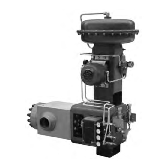
This instruction manual provides installation, operation, maintenance, and parts information for the Fisher Vee-Ball
SS-84PSV4 NPS 4x3 and NPS 5x3 rotary control valve (see figure 1). It also outlines the assembly and testing
procedures for the NPS 4x3 CL2155 and NPS 5x3 CL2075 SS-84PSV4 rotary ball valve designed for use with the
1052PSV size 60 rotary actuator.
The SS-84PSV4 valve is the pressurizer spray valve for use in third generation PWR Nuclear Generating Stations. The
NPS 4x3 valve body has NPS 4 buttweld ends and the NPS 5x3 valve body has NPS 5 buttweld ends. Both valves have
3-inch Fisher Vee-Ball internal trim, which operates against a spring-loaded sleeve seal.
This valve contains several enhanced features compared to the original SS-84 designs which operated in previous PWR
Reactors. These features include the following:
D VeeBall, drive shaft, and actuator lever connections are a missing tooth spline design ensuring One-Way only
assembly.
D Side body flange allows trim removal without actuator removal.
www.Fisher.com
SS-84PSV4
™
. . . . . . . . . . . . . . . . . . . . . . . . .
. . . . . . . . . . . . . . . . . . . . . . . . .
. . . . . . . . . . . . . . . . . . . . . . . .
. . . . . . . . . . . . . . . .
. . . . . . . . . . . . . . . . . . . . .
. . . . . . . . . . . . . . . . .
Figure 1. Fisher SS-84PSV4 Valve
with 1052PSV Actuator and 3610J Positioner
1
1
2
2
2
3
4
6
6
7
12
12
15
15
15
16
17
16
W9722
SS-84PSV4 Valve
September 2022
Advertisement
Table of Contents

Related Manuals for Emerson Fisher Vee-Ball SS-84PSV4


Summary of Contents for Emerson Fisher Vee-Ball SS-84PSV4
-
Page 1: Table Of Contents
Instruction Manual SS-84PSV4 Valve D103416X012 September 2022 Fisher Vee-Ball SS-84PSV4 ™ ™ Rotary Control Valve Contents Figure 1. Fisher SS-84PSV4 Valve with 1052PSV Actuator and 3610J Positioner Introduction ....... . . Scope of Manual . -
Page 2: Description
If you have any questions about these instructions, contact your Emerson sales office before proceeding. Description The SS-84PSV4 Vee-Ball valve (figure 1) with a V‐notch ball is used in throttling or on‐off service. The SS-84PSV4 valve is either a NPS 4 schedule 120 buttweld construction or a NPS 5 schedule 160 buttweld construction. -
Page 3: Installation
Emerson sales office. The valve drive shaft is not necessarily grounded to the pipeline when installed. Personal injury or property damage could result from an explosion caused by a discharge of static electricity from valve components if the process fluid or the atmosphere around the valve is flammable. -
Page 4: Lifting Guidelines
Instruction Manual SS-84PSV4 Valve September 2022 D103416X012 5. The actuator is right‐hand mounted with the shaft in a horizontal orientation as shown in figure 1. If necessary, refer to the appropriate actuator instruction manual for actuator installation and adjustment procedures. NOTICE Ensure the valve and adjacent pipelines are free of foreign material that could damage the valve seating surfaces. - Page 5 Instruction Manual SS-84PSV4 Valve D103416X012 September 2022 NOTICE Care must be taken when lifting the valve/actuator assembly to ensure the accessories and tubing are not damaged in the process. Accessories and tubing may need to be removed prior to lifting to prevent damage and properly reinstalled before use.
-
Page 6: Maintenance
Instruction Manual SS-84PSV4 Valve September 2022 D103416X012 Lifting Valve Only To lift the valve, insert 3/4-10 thread size hoist rings into the two tapped holes on the top of the valve body. These two tapped holes will carry most of the weight, but the assembly must be balanced using one or more straps underneath the valve bottom flange (key 5), as shown in figure 2. -
Page 7: Replacing Packing
Instruction Manual SS-84PSV4 Valve D103416X012 September 2022 Replacing Packing Disassembly WARNING Observe the steps in the WARNING at the beginning of the Maintenance section. 1. Isolate the control valve from the line pressure, release pressure from both sides of the valve body, and drain the process media from both sides of the valve. - Page 8 Instruction Manual SS-84PSV4 Valve September 2022 D103416X012 7. Rotate the VeeBall counterclockwise (ccw) 180_ out of the closed position. This can be accomplished using the following method: a. Use the actuator lever and rotate the drive shaft (key 9) by hand. b.
- Page 9 Instruction Manual SS-84PSV4 Valve D103416X012 September 2022 Assembly If needed, refer to the appropriate sections of the Fisher 1052PSV Size 60 Rotary Actuator Instruction Manual (D103407X012) to connect the valve to the actuator and assemble the actuator. Refer to figure 5 for key number locations during seal installation. Valve key number locations are shown in figure 8. 1.
- Page 10 Instruction Manual SS-84PSV4 Valve September 2022 D103416X012 NOTICE In the following step, if the Vee-Ball is accidentally rotated too far, allowing a gap from the trailing edge of the Vee-Ball, DO NOT rotate counter clockwise (ccw) back into the seat. Continue to rotate around clockwise (cw) and repeat step 15. 12.
- Page 11 Personal injury or damage to equipment could occur if improper stud and nut materials or parts are used. Do not operate or assemble this product with stud(s) and nut(s) that are not approved by Emerson/Fisher engineering and/or listed on the serial card provided with this product.
-
Page 12: Packing Load Adjustment
Instruction Manual SS-84PSV4 Valve September 2022 D103416X012 Stop Screw Gap Settings 1. Apply thread-locking compound (medium strength) (key 77) to the two 3/8-24 x 1.25 stop cap screws (key 17). Install the stop screws with two 3/8-24 jam nuts (key 18) in the stop flange (key 16). Final stop screw lock position will be set with gauged clearance to the packing flange. - Page 13 Instruction Manual SS-84PSV4 Valve D103416X012 September 2022 1. Isolate the control valve from the line pressure, release pressure from both sides of the valve body, and drain the process media from both sides of the valve. If using a power actuator, release pressure from the actuator, disconnect the pressure lines from the actuator.
- Page 14 Personal injury or damage to equipment could occur if improper stud and nut materials or parts are used. Do not operate or assemble this product with stud(s) and nut(s) that are not approved by Emerson/Fisher engineering and/or listed on the serial card provided with this product.
-
Page 15: Troubleshooting
Excessive Ball Seal Leakage Disassemble and inspect Vee-Ball, sleeve seal, and piston ring for excessive wear or scratches. Other Consult your Emerson sales office. Actuator Mounting The actuator is right-hand mounted in a push-down-to-open (PDTO) configuration. 1. Tighten the bolted joints on this valve/actuator assembly using the criss-cross pattern shown in figure 6. Tighten each bolt evenly and in the sequence described. -
Page 16: Parts Ordering
WARNING Use only genuine Fisher replacement parts. Components that are not supplied by Emerson should not, under any circumstances, be used in any Fisher valve, because they may void your warranty, might adversely affect the performance of the valve, and could cause personal injury and property damage. -
Page 17: Spare Parts
Maintenance is a necessary tendency to requirement to ensure positive performance degrade over during the expected life of the valve. Emerson time. recommends replacing this component every 6 years. GE39238 GE39238X012... - Page 18 GH12740 GH12740X012 Piston Ring, Non-Safety Cycled parts will exhibit wear over time. Based on Does not Key 22 Related experience and testing, Emerson recommends exhibit a replacing this component every 12 years. tendency to degrade over time. GE39215 GE39215X022 Packing Non-Safety Cycled parts will exhibit wear over time.
- Page 19 Instruction Manual SS-84PSV4 Valve D103416X012 September 2022 Figure 8. Exploded View, Fisher SS-84PSV4 Valve Body Assembly PARTS NOT SHOWN 23, 28, 93 PARTS NOT USED AGAINST PAINTED SURFACES: 146 j APPLY LUB GE39222-D...
- Page 20 Fisher and Vee-Ball are marks owned by one of the companies in the Emerson Automation Solutions business unit of Emerson Electric Co. Emerson Automation Solutions, Emerson, and the Emerson logo are trademarks and service marks of Emerson Electric Co. All other marks are the property of their respective owners.
Need help?
Do you have a question about the Fisher Vee-Ball SS-84PSV4 and is the answer not in the manual?
Questions and answers