
Related Manuals for Emerson SI-PROFIBUS


Summary of Contents for Emerson SI-PROFIBUS
- Page 1 User Guide SI-PROFIBUS Part Number: 0478-0011-03 Issue Number: 3 www.controltechniques.com...
- Page 2 General Information The manufacturer accepts no liability for any consequences resulting from inappropriate, negligent or incorrect installation or adjustment of the optional parameters of the equipment or from mismatching the variable speed drive with the motor. The contents of this guide are believed to be correct at the time of printing. In the interests of commitment to a policy of continuous development and improvement, the manufacturer reserves the right to change the specification of the product or its performance, or the content of the guide without notice.
-
Page 3: Table Of Contents
Module menu 9 - Resources ................. 45 GSD Files ....................46 What are GSD Files? ..................... 46 Data consistency ....................46 Data configuration ....................46 PROFIBUS DP-V1 ....................47 GSD compatibility table ..................47 Unidrive M SI-PROFIBUS User Guide Issue Number: 3... - Page 4 Setting the non-cyclic mode (non-cyclic over cyclic) ..........83 14.5 Mode 1 - CT Single Word mode ................83 14.6 Reading parameters using CT Single Word ............85 14.7 Mode 2 - PPO 4 Word mode ..................94 Glossary of terms ..................101 Unidrive M SI-PROFIBUS User Guide Issue Number: 3...
-
Page 5: Safety Information
The system designer is responsible for ensuring that the complete system is safe and designed correctly according to the relevant safety standards. Unidrive M SI-PROFIBUS User Guide Issue Number: 3... -
Page 6: Environmental Limits
The drive contains capacitors which remain charged to a potentially lethal voltage after the AC supply has been disconnected. If the drive has been energized, the AC supply must be isolated for at least ten minutes before work may continue. Unidrive M SI-PROFIBUS User Guide Issue Number: 3... -
Page 7: Introduction
This method of communication saves significantly on the amount of cabling required and can improve overall system reliability as the number of interconnections is greatly reduced. Unidrive M SI-PROFIBUS User Guide Issue Number: 3... - Page 8 PROFIBUS master Analog 1 Analog 2 Digital 1A Digital 1B Digital 2A Digital 2B Analog 2 Analog 1 Table 2.2 Data mappings for SI-PROFIBUS Number of Type Source / Destination Description network words digital Inputs slave 1 to master status signals...
-
Page 9: About Si-Profibus
This is the equivalent of a temporary patch lead that is removed after use. About SI-PROFIBUS SI-PROFIBUS is a fieldbus option module that can be installed to the option module slot(s) in any of the following drives to provide PROFIBUS-DP slave connectivity: •... -
Page 10: Option Module Identification
SI-PROFIBUS to continue communicating with the PROFIBUS-DP master controller when the main supply to the drive is switched off. For every SI-PROFIBUS installed allow for an extra 70 mA of supply current to be drawn from the back-up supply. -
Page 11: Conventions Used In This Guide
Pr mm.ppp - Where mm signifies the menu allocated to the option module set-up menu and ppp signifies the parameter number. Pr mm.000 - Signifies parameter number 000 in any drive menu. Unidrive M SI-PROFIBUS User Guide Issue Number: 3... -
Page 12: Mechanical Installation
The above diagram is for illustration only, the actual option module may be different to the one shown here. NOTE Option modules can only be installed on drives that have the option module slot functionality. Unidrive M SI-PROFIBUS User Guide Issue Number: 3... - Page 13 Place the option module onto the drive as shown in (2) until the module clicks into place. The terminal cover on the drive holds the option module in place, so this must now be replaced. Unidrive M SI-PROFIBUS User Guide Issue Number: 3...
- Page 14 • Align and insert the option module tab into the slot provided. This is highlighted in the detailed view (A). • Press down on the option module until it clicks into place. Unidrive M SI-PROFIBUS User Guide Issue Number: 3...
-
Page 15: Electrical Installation
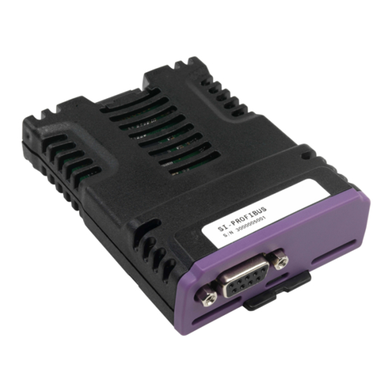
Electrical installation Terminal descriptions SI-PROFIBUS has a standard 9-way female D-type connector for the PROFIBUS-DP network. Figure 4-1 SI-PROFIBUS terminals Table 4.1 SI-PROFIBUS D-Type pin out D-type Terminal Function Description RxD/TxD-P Positive data line (B) - Red RxD/TxD-N Negative data line (A) - Green... -
Page 16: Profibus-Dp Connectors
Failure to terminate a network correctly can seriously affect the operation of the network. NOTE If the correct termination networks are not installed, the noise immunity of the network is greatly reduced. Each network segment must be correctly terminated. Unidrive M SI-PROFIBUS User Guide Issue Number: 3... -
Page 17: Maximum Network Length / Device Loading
1200 Node addressing SI-PROFIBUS has a valid address range of 1 to 125. Addresses 126 and 0 are reserved for system use and should not be used. The addressing scheme used is at the discretion of the end user however it is recommended that nodes are numbered in order as they appear on the physical network. -
Page 18: Getting Started
Getting started This section is intended to provide a generic guide for configuring SI-PROFIBUS with a master controller. Figure 5-1 is intended as a basic guide, but it does detail the stages that are required to achieve a functioning network. It is recommended that all of this chapter is read, before attempting to configure a system. -
Page 19: Set-Up Flow Chart
See Section 5 (Pr S.01.004) Ensure all third party See Section 5 devices use the same data rate A dedicated Perform a network scan PROFIBUS-DP using the master or tester is recommended. tester Unidrive M SI-PROFIBUS User Guide Issue Number: 3... -
Page 20: Single Line Descriptions
Initialized(2), No network data (3), S.01.006 Network Txt ND NC PT First failure (4), Second failure (5), Diagnostic Third Failure (6) Cyclic data S.01.007 transfers per 0 to 9999 messages/s RO Num ND NC PT second Unidrive M SI-PROFIBUS User Guide Issue Number: 3... - Page 21 Input S.01.026 Off (0) or On (1) Off (0) consistency Input S.01.027 consistency 0.00.000 to 4.99.999 0.00.000 RW Num trigger Output S.01.028 Off (0) or On (1) Off (0) consistency Unidrive M SI-PROFIBUS User Guide Issue Number: 3...
- Page 22 0.00.000 to 4.99.999 0.00.000 trigger Non-cyclic over S.01.030 None (0), CTNC (1), PPO defined (2) None (0) cyclic Auto-detect (0), Reserved (1), Compatibility Auto-detect S.01.031 UniSP (2), UniSP extended (3), mode Unidrive Classic (4) Unidrive M SI-PROFIBUS User Guide Issue Number: 3...
- Page 23 RW Num S.02.030 Input source 30 0 to 5.01.004 0.00.000 RW Num S.02.031 Input source 31 0 to 5.01.004 0.00.000 RW Num S.02.032 Input source 32 0 to 5.01.004 0.00.000 RW Num Unidrive M SI-PROFIBUS User Guide Issue Number: 3...
- Page 24 0 to 5.01.004 0.00.000 RW Num DE PT US Output destination S.03.027 0 to 5.01.004 0.00.000 RW Num DE PT US Output destination S.03.028 0 to 5.01.004 0.00.000 RW Num DE PT US Unidrive M SI-PROFIBUS User Guide Issue Number: 3...
- Page 25 S.04.020 Fault value 20 RW Num to 2 S.04.021 Fault value 21 RW Num to 2 S.04.022 Fault value 22 RW Num to 2 S.04.023 Fault value 23 RW Num to 2 Unidrive M SI-PROFIBUS User Guide Issue Number: 3...
- Page 26 2 5.2.6 Menu 9 resources Parameter Range Default S.09.030 PCB temperature 1 -128 °C to 127 °C RO Num ND S.09.031 PCB temperature 2 -128 °C to 127 °C RO Num ND Unidrive M SI-PROFIBUS User Guide Issue Number: 3...
-
Page 27: Parameters
Menu 0 is not available in firmware version 01.01.01.02 and previous versions. NOTE For M200, M300 and M400 drives, the module menu 0 will be displayed in drive menu Table 6.2 SI-PROFIBUS menu 0 locations on M700/M800. Slot number Menu 0 locations... - Page 28 An error has occurred preventing the firmware or user program Error running correctly. Reset module Default Off (0) S.00.007 Range Off (0) or On (1) Access Changes to the SI-PROFIBUS configuration will not take effect until the SI-PROFIBUS has been reset. Unidrive M SI-PROFIBUS User Guide Issue Number: 3...
- Page 29 NOTE This sequence does NOT store the SI-PROFIBUS configuration parameters in the drive or the SI-PROFIBUS flash memory. This parameter will change back to Off (0) immediately and as such the change may not be visible on the display. Default module...
-
Page 30: Module Menu 1 - Profibus Set-Up
Default OFF (0) S.01.002 Range OFF (0) or On (1) Access Changes to the SI-PROFIBUS configuration will not take effect until the SI-PROFIBUS has been reset. To reset the SI-PROFIBUS: • Set Pr S.01.002 to On (1). • When the sequence has been completed, Pr S.01.002 will be reset to OFF (0). - Page 31 Pr S.01.005 will indicate the data rate that has been detected by the SI-PROFIBUS. A value of 0 indicates that the SI-PROFIBUS has not detected any activity on the PROFIBUS-DP network, and is waiting for the master controller to start communicating.
- Page 32 The PROFIBUS-DP network activity can be monitored in the SI-PROFIBUS operating status parameter, Pr S.01.006. When the SI-PROFIBUS is in data exchange with the PROFIBUS-DP master controller, Pr S.01.007 will give an indication of the number of cyclic data messages that are being processed per second. All possible values of S.01.006 are given in Table 6.4.
- Page 33 The network loss detection feature provides a method which detects whether the communication to the master is still present. The SI-PROFIBUS resets an internal timer when a valid message is received from the SI-PROFIBUS network, if a message is not received within the specified period, network loss is detected.
- Page 34 NOTE Network loss detection is not enabled internally until cyclic data has been detected. This prevents spurious network loss timeouts while the SI-PROFIBUS master controller is initializing the PROFIBUS-DP network. Timeout action Default Trip (0) S.01.011 Range Trip (0) to No action (4) Access Pr S.01.011 determines the action to take when a timeout specified by Pr S.01.010...
- Page 35 32 (0) or 16 (1) bits Access By default, the SI-PROFIBUS uses 32 bits for each data channel, even if the target parameter in the drive is a 16-bit parameter. This strategy (known as casting), ensures that the cyclic data transmitted over the SI-PROFIBUS network remains aligned with the memory locations in 32-bit PLC's.
- Page 36 32-bit PLC registers when using auto-mapping facilities to configure the SI-PROFIBUS network. By swapping the mappings for input channel 2 with input channel 3, and moving output channel 5 to output channel 2, the data channel structure will appear as shown in the table below.
- Page 37 If the SI-PROFIBUS network diagnostic parameter (Pr S.01.006) indicates "First Failure" or "Second Failure", a mapping configuration error has been detected. The reason for the error is indicated by the SI-PROFIBUS input mapping status parameter (Pr S.01.022) and the SI-PROFIBUS output mapping status parameter (Pr S.01.023).
- Page 38 Can't configure PPO when data alignment is set to 32 bits No PPO support PPO1-PPO5 not supported Output Mapping can't be set by GSD file automatically in SP A-D OUT map SP mode OUT AND CTNC CTNC and PPO4 not supported PPO4 Unidrive M SI-PROFIBUS User Guide Issue Number: 3...
- Page 39 The SI-PROFIBUS module provides an input/output consistency feature which ensures that the data in the input or output mappings is only transferred between the SI-PROFIBUS module and the master controller when the mapped parameters are ready. This prevents data skew between parameters in the input/output mappings.
- Page 40 If input consistency action (Pr S.01.026) is set to On (1), the SI-PROFIBUS module will check the value of the parameter specified by the input consistency trigger parameter (Pr S.01.027). If the input consistency trigger parameter defined by Pr S.01.027 is set to...
- Page 41 Access SI-PROFIBUS provides a compatibility mode as standard. Pr S.01.031 can be used to select which drive the SI-PROFIBUS module is to appear as on the PROFIBUS network, this only applies to the network identification and not the drive functionality.
-
Page 42: Module Menu 2 - Input Mapping
Pr S.02.022 0.00.000 Pr S.02.023 0.00.000 Pr S.02.024 0.00.000 Pr S.02.025 0.00.000 Pr S.02.026 0.00.000 Pr S.02.027 0.00.000 Pr S.02.028 0.00.000 Pr S.02.029 0.00.000 Pr S.02.030 0.00.000 Pr S.02.031 0.00.000 Pr S.02.032 0.00.000 Unidrive M SI-PROFIBUS User Guide Issue Number: 3... -
Page 43: Module Menu 3 - Output Mapping
Pr S.03.022 0.00.000 Pr S.03.023 0.00.000 Pr S.03.024 0.00.000 Pr S.03.025 0.00.000 Pr S.03.026 0.00.000 Pr S.03.027 0.00.000 Pr S.03.028 0.00.000 Pr S.03.029 0.00.000 Pr S.03.030 0.00.000 Pr S.03.031 0.00.000 Pr S.03.032 0.00.000 Unidrive M SI-PROFIBUS User Guide Issue Number: 3... -
Page 44: Module Menu 4 - Fault Values
Pr S.04.017 Pr S.04.018 Pr S.04.019 Pr S.04.020 Pr S.04.021 Pr S.04.022 Pr S.04.023 Pr S.04.024 Pr S.04.025 Pr S.04.026 Pr S.04.027 Pr S.04.028 Pr S.04.029 Pr S.04.030 Pr S.04.031 Pr S.04.032 Unidrive M SI-PROFIBUS User Guide Issue Number: 3... -
Page 45: Module Menu 9 - Resources
-128°C to 127°C Access PCB temperature 2 Default Range S.09.031 -128°C to 127°C Access Parameters Pr S.09.030 and Pr S.09.031 display the current temperature of the 2 internal thermistors within the option module. Unidrive M SI-PROFIBUS User Guide Issue Number: 3... -
Page 46: Gsd Files
The SI-PROFIBUS module uses Pr S.01.020 and Pr S.01.021 to independently set the number of input and output words respectively. The definition of a data word is 16 bits. By default SI-PROFIBUS casts all data as long NOTE words/double words (32 bits), data alignment can be used to reduce this size, see section S.01.014 on page 35 for more information. -
Page 47: Profibus Dp-V1
CTUD0EA5.GSD Unidrive SP UniSP SP_ _0672.GSD Unidrive SP with extended diagnostics UniSP extended SP_ _0B4F.GSD Unidrive Classic Unidrive Classic CTU_ _3345.GSD NOTE Unidrive M200/M300/M400 are not supported in version V01.02.00.02 or earlier. Unidrive M SI-PROFIBUS User Guide Issue Number: 3... -
Page 48: Cyclic Data
PROFIBUS-DP network and using local mapping information within the SI-PROFIBUS and PROFIBUS-DP master controller to ensure that the correct data is sent to the correct locations. The flexibility of the SI-PROFIBUS means that each cyclic data OUT channel can be directed to any read/write drive parameter. Similarly each cyclic data IN channel can use any drive parameter as a source of data. - Page 49 If a mapping parameter is set to an invalid value (e.g. the destination parameter is read only, or the parameter does not exist), the SI-PROFIBUS will indicate a failure error in the PROFIBUS Network diagnostic parameter (Pr S.01.006). The reason for the failure error will be indicated by the mapping status parameter (Pr S.01.022) and (S.01.023).
-
Page 50: Mapping Conflicts
• Variable selected outputs The SI-PROFIBUS will not indicate if there is a mapping conflict due to any one of the reasons listed. Should a conflict occur and a parameter is written to from two or more different sources, the value of this parameter will depend entirely upon the scan times for the function and the PROFIBUS-DP network. -
Page 51: Disabling Mappings
Failure”). Master configuration The SI-PROFIBUS mapping parameters can be automatically configured by the master controller. If Pr S.01.008 is set to Auto, then the Input cyclic words (Pr S.01.020), Output cyclic words (Pr S.01.021), Input source mappings (Pr S.02.ppp) and Output destination mappings (Pr S.03.ppp) will be set by the master controller using the... -
Page 52: Non-Cyclic Data
SI-PROFIBUS has been reset. SI-PROFIBUS can be reset by writing a value of 1 to Pr MM.007. A brief interruption in PROFIBUS-DP communications may be seen while the reset sequence is in progress. - Page 53 SI-PROFIBUS supports the following features: • DP-V1 Parameter Access • PROFIdrive PNU Access (see section 12.11 PROFIdrive PNU access on page 75) • Fault Buffer (see section 12.12 Fault Buffer on page 76) • Drive Identification (see section 12.13 Drive Identification on page 78) •...
- Page 54 PROFIdrive Parameters (PNU’s) can be accessed by placing the PNU number in the parameter index field and if the PNU data type is an array, then the sub-index field may also be specified. Unidrive M SI-PROFIBUS User Guide Issue Number: 3...
-
Page 55: Control And Status Words
10.2 Control word The SI-PROFIBUS control word consists of sixteen control bits some of which are reserved. See Table 10.1 for the individual bit function descriptions. Table 10.1 Control word bit definitions... - Page 56 Set to 1 to trip the drive at any time. The trip display on drive will be TRIP CL.bit and the trip code will be 35. AUTO (b7) has no effect on this function. The trip cannot be cleared until TRIP is reset to 0. Unidrive M SI-PROFIBUS User Guide Issue Number: 3...
-
Page 57: Status Word
SLC trip occurs, and so it must be re-enabled when the trip is reset. Reserved 10.3 Status word The SI-PROFIBUS status word consists of sixteen control bits some of which are reserved. See Table 10.3 for the individual bit function descriptions. Table 10.3 Status word bit definitions Reverse... - Page 58 Regen mode: Indicates that power is being transferred from the drive to the supply. Dynamic brake active Pr 10.011 Indicates that the braking IGBT is active. If the IGBT becomes active, this parameter will remain on for at least one second. Unidrive M SI-PROFIBUS User Guide Issue Number: 3...
- Page 59 DC bus voltage. This parameter can only become Pr 10.015 active if supply loss ride through or supply loss stop modes are selected. In regen mode, supply loss is the inverse of Pr 03.007. (Not Used) Reserved Unidrive M SI-PROFIBUS User Guide Issue Number: 3...
-
Page 60: Diagnostics
11.2 Drive trip display codes If the SI-PROFIBUS module detects an error during operation, it will force a trip on the drive. However, the trip string displayed on the drive will only indicate which slot initiated the trip. The exact reason for the trip will be indicated in the drive trip code parameters (Pr 10.020 and Pr 10.070). - Page 61 11.2.1 Module error codes If the SI-PROFIBUS detects an error during operation it will force a drive trip. Table 11.2 shows all the possible SI-PROFIBUS error codes. Table 11.2 SI-PROFIBUS error codes Value Text Description No trip No trip SW fault...
- Page 62 11.2.3 SI-PROFIBUS network diagnostic The operating status of the SI-PROFIBUS module can be viewed in the network diagnostic parameter (Pr S.01.006). All possible values of this parameter are described in Table 11.4. Table 11.4 SI-PROFIBUS operating status Value Text Description Network OK Network OK/healthy.
- Page 63 Can’t configure PPO when data alignment is set to 32 bits No PPO support PPO1-PPO5 not supported SP A-D OUT map Output Mapping can’t be set by GSD file automatically in SP mode OUT AND CTNC CTNC and PPO4 not supported PPO4 Unidrive M SI-PROFIBUS User Guide Issue Number: 3...
- Page 64 Check set-up flowchart and double check all drive settings. Before calling for support ensure you have all drive and option module parameters and firmware versions Unidrive M SI-PROFIBUS User Guide Issue Number: 3...
-
Page 65: Profidrive Profile (V4)
For further details of the PROFIdrive profile refer to the official PROFIBUS web-site at www.profibus.com. The SI-PROFIBUS module provides support for the “Standard Drive” application class 1 defined in the PROFIdrive V4 specification for speed control mode using Standard Telegram 1. -
Page 66: Main Setpoint
Where SF is the speed feedback parameter, i.e. Pr 02.001 or Pr 03.002 depending upon the drive operating mode. Example 1 - Open loop drive The drive maximum speed clamp (Pr 01.006) = 50.0 Hz The drive post ramp reference (Pr 02.001) = 35.0 Hz Unidrive M SI-PROFIBUS User Guide Issue Number: 3... -
Page 67: Profidrive (V4) State Machine
There is a priority control hierarchy when more than the one stop command is given, these priorities are shown in the general state machine diagram and summarized in Table 12.2 on page 68. Unidrive M SI-PROFIBUS User Guide Issue Number: 3... - Page 68 Quick stop (Pr 02.022) 1 (low) Ramp stop (Pr 02.021) 0 (lowest) Disable Operation The deceleration rates are set in Pr 02.021 and Pr 02.022 for Ramp Stop and Quick Stop NOTE respectively. Unidrive M SI-PROFIBUS User Guide Issue Number: 3...
- Page 69 Figure 12-1 PROFIdrive V4 General State Machine Diagram Unidrive M SI-PROFIBUS User Guide Issue Number: 3...
- Page 70 Figure 12-2 PROFIdrive V4 Speed Control State Machine Unidrive M SI-PROFIBUS User Guide Issue Number: 3...
-
Page 71: Stopping The Motor Using Profidrive
• Set jog direction reverse (bit 8=0 and bit 9=1, 0x060F) • Set jog setpoint value (Pr 01.005) The motor should now jog at the speed set by the jog setpoint value. Unidrive M SI-PROFIBUS User Guide Issue Number: 3... -
Page 72: Profidrive Control Word
Group signal is acknowledged at a positive edge; the Fault drive is in the ‘fault’ status until the fault has been Acknowledge removed and then goes into ‘switch-on inhibit’ state. No meaning Unidrive M SI-PROFIBUS User Guide Issue Number: 3... -
Page 73: Profidrive Status Word
Fault number in the fault parameter. No Fault Present Drive ok Coast Stop Not Coast Stop command is not active. Activated Coast Stop Coast Stop command is active. Activated Unidrive M SI-PROFIBUS User Guide Issue Number: 3... - Page 74 ‘At Speed’ (Pr 10.006) = 1 or Reached/ ‘Above Set Speed’ (Pr 10.007) = 1 Exceeded Speed Or ‘At Speed’ (Pr 10.006) = 0 and Frequency Not ‘Above Set Speed’ (Pr 10.007) = 0 Reached 11-15 Reserved Unidrive M SI-PROFIBUS User Guide Issue Number: 3...
-
Page 75: Profidrive Pnu Access
The full list of supported PROFIdrive PNUs is shown in Table 12.5. Table 12.5 Supported PROFIdrive PNUs Designation Data type Access Explanation Returns the SI-PROFIBUS network node 918 PROFIBUS Node ID Unsigned16 address. Device system The device system number is a Visible string 16... -
Page 76: Fault Buffer
Unacknowledged faults are faults which have not been cleared, currently Control Techniques drives only support one fault of this type, the active fault in Pr 10.020. The PROFIdrive fault buffer mechanism is shown in Figure 12-3 on page 77. Unidrive M SI-PROFIBUS User Guide Issue Number: 3... - Page 77 Defines the number of fault situations and the number of faults per situation. (factory set to 8 and 1 respectively) The fault buffer contents are stored in internal memory and will be cleared on a module NOTE reset or power-down. Unidrive M SI-PROFIBUS User Guide Issue Number: 3...
-
Page 78: Drive Identification
12.13 Drive Identification The PROFIdrive specification specifies certain objects that allow network tools to obtain information on the features supported by the slave. SI-PROFIBUS supports the following PNU’s for this purpose. Table 12.7 Identification PNU’s Designation Description Drive Unit Identification... -
Page 79: Advanced Features
13.3 Multi-master operation The SI-PROFIBUS can be used on PROFIBUS-DP networks containing one or more master controllers. Consult your master controller documentation for information on how to configure a multi-master PROFIBUS-DP network. Users must ensure that in networks with multiple master devices that only one master NOTE controller is configured to access the SI-PROFIBUS. -
Page 80: Legacy Features
Access SI-PROFIBUS provides a compatibility mode as standard. Pr S.01.031 can be used to select which drive the SI-PROFIBUS module is to appear as on the PROFIBUS network, this only applies to the network identification and not the drive functionality. -
Page 81: Ppo Types
14.2 PPO Types SI-PROFIBUS supports all five types of Parameter Process data Object (PPO) defined by the PROFIdrive profile V4. The PROFIdrive profile features four specific functions which the SI-PROFIBUS translates into appropriate drive functions: • PROFIdrive control word •... - Page 82 9 word 9 using using word 10 word 10 Pr S.02.004 to Pr S.02.020 Pr S.03.004 to Pr S.03.020 word 11 word 11 word 12 word 12 word 13 word 13 Unidrive M SI-PROFIBUS User Guide Issue Number: 3...
-
Page 83: Configuring The Profile
• Set mm.000 to Save parameters or 1000 and press the reset button. • S.01.002 or Pr MM.007 set to On to reset SI-PROFIBUS • Check Pr S.01.006 doesn't indicate a fault (see Table 6.4 on page 32 for further details) Save the drive parameters (refer to the relevant drive documentation for more information). - Page 84 3. Set S.01.002 or Pr MM.007 to ON to reset. When the SI-PROFIBUS resets, it will map cyclic data IN Word 0 and cyclic data OUT Word 0 to the CT Single Word protocol parameter. All existing mapping parameters will be moved down by one word, (i.e.
-
Page 85: Reading Parameters Using Ct Single Word
• Telegram 3 - request high data byte • Telegram 4 - request mid-high data byte • Telegram 5 - request mid-low data byte • Telegram 6 - request low data byte Unidrive M SI-PROFIBUS User Guide Issue Number: 3... - Page 86 IN word back to the PLC. This is the signal to the master controller program that the first telegram of the message has been received and understood the second telegram can now be transmitted. Unidrive M SI-PROFIBUS User Guide Issue Number: 3...
- Page 87 If an error is reported, the non-cyclic data word should be set to 0 to ensure that the NOTE non-cyclic state machine is completely reset and ready for the next non-cyclic READ or WRITE sequence. Unidrive M SI-PROFIBUS User Guide Issue Number: 3...
- Page 88 Example response b15-b12 b11-b8 b7-b4 b3-b0 Value 1001 0100 0000 0001 Data word = 0x9401 Stamp number = 4 Data mid-high byte = 0x01 = 1 Unidrive M SI-PROFIBUS User Guide Issue Number: 3...
- Page 89 Example response b15-b12 b11-b8 b7-b4 b3-b0 Value 1001 0110 1101 1100 Data word = 0x96DC Stamp number = 6 Data low byte = 0xDC = 220 Unidrive M SI-PROFIBUS User Guide Issue Number: 3...
- Page 90 OK telegram Tx_Stamp_No = 6? END OF SEQUENCE The following telegrams show how to set the digital speed reference 1 (Pr 01.021) to 12553.9 rpm (32-bit value is 125539) in the drive. Unidrive M SI-PROFIBUS User Guide Issue Number: 3...
- Page 91 IN word. This is the signal to the master controller program that the third telegram of the message has been received and understood and the fourth telegram can be transmitted. Unidrive M SI-PROFIBUS User Guide Issue Number: 3...
- Page 92 (Pr 01.021 = 12553.9) as transmitted (the decimal point is automatically inserted when the data is transferred to the drive). If the operation is successful, the ERR bit is reset to 0 and the telegram is reflected in the non-cyclic IN word. Unidrive M SI-PROFIBUS User Guide Issue Number: 3...
- Page 93 16-bit value, the ERR bit will be set. When writing data to a 32-bit parameter, the 16-bit data will be treated as a signed 16-bit data value. This limits the range that can be written to a 32-bit parameter. Unidrive M SI-PROFIBUS User Guide Issue Number: 3...
-
Page 94: Mode 2 - Ppo 4 Word Mode
3. Save the parameters if required (see the relevant drive documentation for information on saving drive parameters). When the SI-PROFIBUS resets, it will map cyclic data IN words 0 to 3 and OUT words 0 to 3 to the PPO 4 Word protocol parameter. All existing mapping parameters will be moved down by one mapping, (i.e. - Page 95 0, a value over-range error will be reported. Request last Returns the last parameter for the specified menu. parameter Specify MENU. (Values in PARAMETER, DATA HIGH reference word and DATA LOW word will be discarded.) Unidrive M SI-PROFIBUS User Guide Issue Number: 3...
- Page 96 ID 8 is read only, and cannot be modified. If RESPONSE ID 7 has been received, the error code can be read from word 3. This will indicate the reason why the TASK ID request failed (see Table 14.18). Unidrive M SI-PROFIBUS User Guide Issue Number: 3...
- Page 97 MENU in OUT Word 0 END OF SEQUENCE Table 14.19 shows the possible TASK ID and RESPONSE ID combinations that may be seen when attempting to read a parameter value from a drive. Unidrive M SI-PROFIBUS User Guide Issue Number: 3...
- Page 98 Care should be taken to ensure the parameters for the read are set-up before the TASK ID is changed from 0 to prevent incorrect data in the returned value. Unidrive M SI-PROFIBUS User Guide Issue Number: 3...
- Page 99 TASK ID 8 could not be executed. Check Write Parameter the error code in IN word 3 for the reason Value (32-bit) why. Write Parameter Parameter is read only, and cannot be Value (32-bit) written to. Unidrive M SI-PROFIBUS User Guide Issue Number: 3...
- Page 100 CT Single Word and/or the PPO 4 Word modules must be selected. A total of eight different modules can be selected to configure the input and output configuration of the node. Unidrive M SI-PROFIBUS User Guide Issue Number: 3...
-
Page 101: Glossary Of Terms
A typical use of cyclic data would be the transmission of a speed reference or a control word. Data alignment: By default SI-PROFIBUS transmits values as 32 bits on the network. It is possible by using data alignment to reduce the number of bits transmitted when sending 16-bit (or smaller) values on the network to 16-bit (32-bit values will still be transmitted as 32 bit values). - Page 102 Double word: A 32-bit word, this may be signed or unsigned. DPV 0,1,2: This describes the specification version of SI-PROFIBUS used. Grounding/Earthing: Describes the electrical safety or shielding connections for the module. Endian format: When a value uses more than eight bits to represent its value it needs to be sent in sets of eight bits (bytes) across the network, the endian format determines the order the bytes that constitute the whole value are transmitted.
- Page 103 Watchdog: A method used to determine if a communication system is ok. A typical watchdog scheme uses a handshaking system to check both the master and slave are participating in communications. Word: A collection of 16 binary digits. Unidrive M SI-PROFIBUS User Guide Issue Number: 3...
- Page 104 Index Numerics 16-bit parameter access ................93 2 cyclic channels only .................49 Abort CT single word ..................93 Above set speed ..................58 At speed .....................58 Below set speed ..................58 Cable ......................16 Cable shield connections ................16 Cautions .......................5 Compliance ....................6 Configuring the profile ................81 Connectors ....................16 Consistency ....................46 Control word ....................55...
- Page 105 PPO 4 word mode ..................94 PPO 4 word read ..................97 PPO 4 word write ..................99 PPO 5 ......................82 PPO types ....................65 PROFIBUS DP-V1 Overview ..............52 PROFIdrive (V4) State Machine ..............67 PROFIdrive control word ................72 Unidrive M SI-PROFIBUS User Guide Issue Number: 3...
- Page 106 PROFIdrive PNU access ................75 PROFIdrive profile ..................65 PROFIdrive status word ................73 PROFIdrive V4 General State Machine Diagram ........69 PROFIdrive V4 Speed Control State Machine Diagram ......70 Reading parameters using CT Single Word ..........85 Regenerating ....................58 Running at or below minimum speed ............58 Safety of personnel ..................5 Set-up flow chart ..................19 Single word ....................100...
- Page 108 0478-0011-03...
Need help?
Do you have a question about the SI-PROFIBUS and is the answer not in the manual?
Questions and answers