Table of Contents
Advertisement
Available languages
Available languages
Quick Links
Advertisement
Table of Contents

Related Manuals for Vortice VORT HRI DH Series


Summary of Contents for Vortice VORT HRI DH Series
- Page 1 Libretto Istruzioni Instruction Booklet VORT HRI DH COD. 5.471.084.696 23/05/2017...
-
Page 2: Table Of Contents
Structure and items included ......30 these instructions carefully. Vortice will not accept Operating mode ........32 any responsibility for damage to property or Installation . -
Page 3: Descrizione Ed Impiego
ITALIANO Descrizione ed impiego Vort HRI DH (nel seguito “l’apparecchio”) è un deumidificatore con recupero di calore ad altissima efficienza, progettato per garantire la deumidificazione ed il rinnovo dell’aria in ambienti residenziali ad altissima efficienza energetica, in abbinamento con sistemi di raffrescamento radiante. L’apparecchio è... -
Page 4: Sicurezza
• In caso di cattivo funzionamento e/o guasto dell'apparecchio, rivolgersi subito ad un Centro di Assistenza autorizzato Vortice e richiedere, per l’eventuale riparazione, l'uso di ricambi originali Vortice. • Se l’apparecchio cade o riceve forti colpi farlo verificare subito presso un Centro di Assistenza Tecnica autorizzato Vortice. -
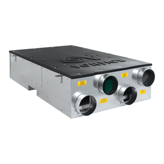
Page 5: Struttura E Dotazione
ITALIANO • Per poter consentire il corretto funzionamento dell’apparecchio deve essere garantita all’unità una portata d’aria costante prossima al valore nominale dichiarato. Lo spostamento massimo consentito è del 10 . • Ai fini del contenimento della rumorosità è necessario che la velocità dell’aria all’interno dell’apparecchio non superi i 4 m/sec. - Page 6 ITALIANO Termostato (solo nella versione con Termo-Igrostato meccanico remoto). Il quadro elettrico viene fornito completo di 3 trimmers di regolazione per i ventilatori, che vengono utilizzati in fase di avviamento impianto per tarare le portate d’aria dei ventilatori in funzione delle perdite di carico delle canalizzazioni: micro-switch di regolazione portata di espulsione;...
-
Page 7: Modalità Di Funzionamento
ITALIANO Modalità di funzionamento Funzionamento estivo (compressore attivo) con aria esterna Impostando questa funzione, l’unita rinnova l’aria ambiente con quella esterna attraverso il recuperatore di calore ad altissima efficienza. Le funzioni possibili in questa configurazione sono: Rinnovo + Deumidificazione ad aria neutra: l’unita condensa parzialmente in aria e parzialmente in acqua tramite il condensatore a piastre, ottenendo aria deumidificata e termicamente neutra. -
Page 8: Installazione
ITALIANO Installazione L’apparecchio deve essere installato a soffitto. L’unità viene sospesa tramite staffe; queste ultime devono essere collegate agli antivibranti, che devono essere selezionati in funzione del tipo di struttura a cui vanno fissati. E’consigliato rivestire l’interno del controsoffitto con materiale fonoassorbente ad alta densità e prevedere una o più aperture per l’estrazione e la successiva pulizia dei filtri aria, per il controllo del circuito frigorifero, la manutenzione e il controllo del quadro elettrico. - Page 9 ITALIANO N.B. Nella linea di scarico deve essere realizzato un sifone che dovrà avere battente minimo pari alla prevalenza in aspirazione del ventilatore, in ogni caso mai inferiore a 35 mm. Collegamento idraulico alla batteria ad acqua Il deumidificatore deve essere collegato all’impianto acqua refrigerata per garantire l’immissione in ambiente di aria in condizione neutra o raffreddata.
- Page 10 ITALIANO Collegamento ai canali d’aria L’apparecchio deve essere collegato alle canalizzazioni d’aria in modo da poter di immettere aria trattata nelle camere da letto e nel soggiorno e di aspirare aria dai locali piu inquinati (cucina, bagni). Il trasferimento dell’aria attraverso i locali avviene generalmente attraverso le fessure presenti sotto le porte, non sono, di norma, richieste griglie di ripresa.
- Page 11 ITALIANO MS3: regolazione del ventilatore di espulsione. N.B. Ai fini del contenimento della rumorosità, è necessario che la velocità dell’aria nelle canalizzazioni NON superi mai i 4 m/sec. Inoltre con velocità di attraversamento elevate, si riduce notevolmente la capacità di deumidificazione dell’unità ed aumenta il rischio di trascinamento d’acqua di condensazione nei canali d’aria con potenziale danneggiamento del mobilio e/o pavimentazioni.
-
Page 12: Collegamenti Elettrici
ITALIANO Collegamenti elettrici Apparecchio abbinato a termoigrostato meccanico Alimentazione unità L’apparecchio è alimentato con tensione 230/1/50; si raccomanda di interporre un sezionatore generale sulla linea di alimentazione. Riferirsi allo schema elettrico per il dimensionamento. (fig 15) Commutazione stagionale remota estate/inverno Viene utilizzato per commutare la modalita di funzionamento dell’unita. - Page 13 ITALIANO Pompa acqua Deve essere collegata ai morsetti 26 e N1; con assorbimento massimo di corrente di 1A. Nel caso di assorbimenti elettrici maggiori e necessario utilizzare un adeguato relè. Nella configurazione standard, il controllo a microprocessore spegne la pompa acqua al raggiungimento del set point. Questa soluzione permette una importante riduzione della potenza elettrica assorbita quando il set point e raggiunto o l’unita è...
- Page 14 ITALIANO Apparecchio abbinato a sonda elettronica di umidità/temperatura Tale sonda è utilizzabile per misurare la temperatura e l’umidità relativa presente in ambiente. Essa dialoga direttamente con il controllo a microprocessore dell’unita e in funzione delle letture fatte attiva le varie modalità di funzionamento. 01-02 : Alimentazione sonda 7-43 : Sonda umidita 70-71 : Sonda temperatura...
- Page 15 ITALIANO Commutazione stagionale remota estate/inverno Viene utilizzato per la commutazione remota estate/inverno. Le unita sono fornite di serie dalla fabbrica con morsetti non ponticellati. I collegamenti devono essere liberi da potenziale. Contatto chiuso: unita in modalità INVERNO. Contatto aperto: unita in modalità ESTATE. (fig.
-
Page 16: Messa In Funzione
ITALIANO Messa in funzione Descrizioine del controllore (fig.28) Tasto UP (navigazione a menù, scorrimento pa- rametri, scorrimento valori parametri..) Tasto modalità estate Tasto DOWN (navigazione a menù, scorrimento pa- Tasto modalità inverno rametri, scorrimento valori parametri..) Tasto SET (visualizzazione set-point, accesso ai Tasto MENU’... - Page 17 ITALIANO Funzione dei tasti (fig.30) M Pressione e rilascio: permette di accedere al menu funzioni SET Pressione e rilascio in visualizzazione principale: consente la visualizzazione dei set point; Set di umidità estivo, e nella riga inferiore del display apparirà la scritta SETU. Set di umidità...
- Page 18 ITALIANO Pannello comandi remoto (fig.31) Installazione Il terminale remoto va montato a pannello, su foro 72x56 mm, e fissato con viti. Per ottenere una protezione frontale IP65 utilizzare la gomma di protezione frontale mod. RGW-V (opzionale). Per il fissaggio a muro e’ disponibile un adattatore per tastiere verticali V-KIT.
- Page 19 ITALIANO Icone del display Fig.33 ICONA FUNZIONE Accese quando il display visualizza una temperatura oppure una pressione. (°C = gradi Celsius; °F = gradi Fahrenheit; BAR = pressione in Bar; PSI = pressione in Psi) Conteggio dell’intervallo tra sbrinamenti. Presenza di allarme (lampeggiante). Accesa durante l’accesso al menù...
- Page 20 ITALIANO Funzione dei tasti Fig 34 M Pressione e rilascio: permette di accedere al menu funzioni SET Pressione e rilascio in visualizzazione principale: consente la visualizzazione dei set point; Set di umidità estivo, e nella riga inferiore del display apparirà la scritta SETU. Set di umidità...
- Page 21 ITALIANO Sonda elettronica di umidità/temperatura (fig.36) 120 mm La sonda elettronica ambiente va installata nell’ambiente da trattare a circa 1,2 - 1,5 mt di altezza dal pavimento in posizione tale da non ricevere irraggiamenti o correnti d’aria esterna. Il collegamento elettrico deve essere eseguito come da schema precedentemente illustrato utilizzando cavi elettrici schermati aventi sezione 0,5 mm2.
-
Page 22: Utilizzo
ITALIANO Utilizzo Accensione e primo avviamento Per alimentare elettricamente l’unita, girare l’interruttore generale in posizione ON. Fig. 37: con sonda umidita ambiente il display mostra temperatura ambiente (in alto) e umidita ambiente (in basso). Fig. 38: con termoumidostato il display mostra consenso temperatura off (tOFF) o consenso temperatura on (tOn) in alto e consenso umidita off (UOFF) o consenso umidita on (UOn) in basso. - Page 23 ITALIANO Selezionare il set point richiesto premendo il tasto . In basso nel display appaiono i seguenti simboli: SEtU Set point umidita estate; SEtI Set point modalita inverno; SEtC Set point temperatura estate; SEtH Set point temperatura inverno Per impostare il set point richiesto premere ancora il tasto per 3 secondi.
-
Page 24: Manutenzione/Pulizia
ITALIANO Manutenzione e pulizia N.B. Tutte le operazioni descritte in questo capitolo DEVONO ESSERE SEMPRE ESEGUITE DA PERSONALE QUALIFICATO. Prima di effettuare qualsiasi intervento sull’unita o di accedere a parti interne, assicurarsi di aver sconnesso l’alimentazione elettrica. Le testate e la tubazione di mandata del compressore si trovano di solito a temperature piuttosto elevate. Prestare particolare cautela quando si opera in prossimita delle batterie. - Page 25 ITALIANO Pulizia scambiatore Estrarre lo scambiatore dopo aver aperto il pannello (fig. 45,46)) MOD 260 MOD 500 N.B. Per la pulizia del recuperatore non usare acqua. E’ pero possibile pulire con un aspirapolvere la parte posteriore del recuperatore dopo averlo estratto come indicato in figura. Riparazione circuito frigorifero Il sistema deve essere caricato con azoto usando una bombola munita di valvola riduttore, fino alla pressione di circa 15 bar.
-
Page 26: Diagnosi E Risoluzione Dei Problemi
ITALIANO Diagnosi e risoluzione dei problemi L’apparecchio è verificato e collaudato in fabbrica prima della spedizione, tuttavia è possibile che si verifichi durante il funzionamento qualche anomalia o guasto. N.B. Si raccomanda di resettare un codice di allarme solo dopo aver rimosso la causa che lo ha generato; reset ripetuti possono determinare danni irreversibili all’apparecchio. -
Page 27: Informazione Importante Per Lo Smaltimento Ambientalmente Compatibile
ITALIANO Informazione importante per lo smaltimento ambientalmente compatibile IN ALCUNI PAESI DELL'UNIONE EUROPEA QUESTO PRODOTTO NON RICADE NEL CAMPO DI APPLICAZIONE DELLA LEGGE NAZIONALE DI RECEPIMENTO DELLA DIRETTIVA RAEE E QUINDI NON È IN ESSI VIGENTE ALCUN OBBLIGO DI RACCOLTA DIFFERENZIATA A FINE VITA. Questo prodotto è... -
Page 28: Description And Use
ENGLISH Description and use Vort HRI DH (hereinafter “the appliance”) is a very high-efficiency, heat-recovery dehumidifier designed to ensure dehumidification and air renewal in very highly energy-efficient residential environments, in conjunction with radiant cooling systems. The appliance comprises a direct expansion chiller circuit combined with an extremely efficient crossed flow heat recovery unit designed to ensure heat recovery and ambient air renewal. -
Page 29: Safety
• Regularly inspect the appliance for visible defects. If any faults are found, do not operate the appliance but contact a Vortice authorised Technical Support Centre immediately. • If the appliance malfunctions and/or develops a fault, contact a Vortice authorised Technical Support Centre immediately. Ensure that only genuine original Vortice spares are used for any repairs. -
Page 30: Structure And Items Included
ENGLISH dehumidification capacity and increase the risk of entrainment of condensate into the air ducts, with potential damage to furniture and/or flooring. • Specifications for the power supply must correspond to the electrical data on ID plate A (Fig.3). The appliance must be installed by a professionally qualified electrician. •... - Page 31 ENGLISH maximum outlet airflow control trimmer. Control and protection devices The appliance is equipped with the following control and protection devices: 1. Defrost thermostat: alerts the microprocessor of the need to run a defrosting cycle, and determines it duration. 2. Limit sensor: alerts the microprocessor of the fact that the temperature limit has been exceeded (pre-post coil inlet water).
-
Page 32: Operating Mode
ENGLISH Operating mode Summer operating mode (compressor ON) with outdoor air By setting this operating mode, the unit renews the indoor air with outdoor air by means of the very high-efficiency heat recovery unit. The possible functions in this configuration are as follows: Renewal + dehumidification with neutral air: the unit condenses partially in air and partially in water by means of the plate capacitor, thereby generating thermally neutral, dehumidified air. -
Page 33: Installation
ENGLISH Installation The appliance must be ceiling-mounted. The unit is hung on brackets; the latter must be connected to the vibration dampers, which must be selected according to the type of structure to which they are to be fixed. You are advised to line the inside of the false ceiling with high-density sound-absorbing material, and create one or more openings for removing and cleaning the air filters, checking the chiller circuit, and inspecting and maintaining the electrical panel. - Page 34 ENGLISH N B A siphon must be created in the drainage line. This must have a minimum pressure head equal to the intake pressure of the fan, and in any case no less than 35 mm. Water connection to the water coil The dehumidifier must be connected to the chilled water system to ensure that thermally neutral or cooled air can be introduced into the room.
- Page 35 ENGLISH Connection to the air ducts The appliance must be connected to the air ducts so that treated air can be introduced into the bedrooms and living room, and drawn out of the most polluted rooms (kitchen, bathrooms). Air is generally transferred between rooms via the cracks under the doors. As such, intake grilles are not normally necessary.
- Page 36 ENGLISH MS2: regulation of the supply fan in winter mode. MS3: regulation of the exhaust fan. N B In order to keep noise reduction, it is necessary that the air speed in the duct system does never exceed 4 m/sec. In addition, with high crossing speed the dehumidification capacity of the unit is extremely reduced and the risk of dragging the condensation water in the air channels increases with a possible damage to the furnitures and / or the floors.
-
Page 37: Electrical Connections
ENGLISH Electrical connections Appliance combined with mechanical thermo-hygrostat Unit supply voltage The appliance is powered with a voltage of 230/1/50; a disconnector should be fitted on the power supply wire. Please refer to the wiring diagram for sizing. (fig 15) Remote summer/winter switchover Used for switching the unit's operating mode. - Page 38 ENGLISH Water pump The water pump must be connected to terminals 26 and N1; with maximum current consumption of 1A. For higher electrical consumption, it is necessary to use an appropriate relay. In standard configuration, the microprocessor control switches off the water pump when the set-point is reached.
- Page 39 ENGLISH Appliance combined with electronic humidity/temperature sensor This sensor can be used to measure the temperature and relative humidity in the room. It communicates directly with the unit's microprocessor controller and activates the various operating modes according to the readings it takes. 01-02: Sensor power supply 7-43: Humidity sensor 70-71: Temperature sensor...
- Page 40 ENGLISH Remote summer/winter switchover Used for remote summer/winter switching. The units are supplied as standard with non-jumpered terminals. The connections must be potential-free. Contact closed: unit in WINTER mode. Contact open: unit in SUMMER mode. (fig. 25) This contact must be ABSOLUTELY operated by switch or other device that controls the closing and opening.
-
Page 41: Start-Up Procedure
ENGLISH Start-up procedure Description of the controller (fig.28) UP button (navigate using menus, scroll Tasto UP through parameters, scroll through (navigazione a menù, scorrimento pa- parameter values, etc.) Summer operating mode button rametri, scorrimento valori parametri..) Tasto modalità estate DOWN button (navigate using menus, scroll Tasto DOWN through parameters, scroll through... - Page 42 ENGLISH Button functions (fig.30) BUTTON FUNCTION M Press and release to access the functions menu M Pressione e rilascio: permette di accedere al menu funzioni SET Press and release in main view: SET Pressione e rilascio in visualizzazione principale: displays the set-points; consente la visualizzazione dei set point;...
- Page 43 ENGLISH Remote control panel (fig.31) Installation The remote terminal must be fitted on the panel, on a 72x56 mm hole, and secured with screws. To obtain frontal ingress protection to IP65, use the rubber front protection pad mod. RGW-V (optional). For the purposes of wall mounting, an adapter is available for V-KIT vertical keypads.
- Page 44 ENGLISH Display icons Fig.33 ICON FUNCTION ICONA FUNZIONE Lit when the display shows a temperature or pressure Accese quando il display visualizza una temperatura oppure una pressione. (°C = degrees Celsius; °F = degrees Fahrenheit; BAR = pressure in Bar; PSI = pressure in Psi) (°C = gradi Celsius;...
- Page 45 ENGLISH Button functions Fig 34 BUTTON FUNCTION M Press and release to access the functions menu M Pressione e rilascio: permette di accedere al menu funzioni SET Press and release in main view: SET Pressione e rilascio in visualizzazione principale: displays the set-points;...
- Page 46 ENGLISH Electronic humidity/temperature sensor (fig.36) 120 mm The electronic room humidity/temperature sensor must be installed in the room to be treated at a height of about 1.2 to 1.5 m above the ground in a position in which it will not exposed to radiation or draughts of outdoor air.
-
Page 47: Use
ENGLISH Switching on and first start-up To power up the unit, turn the main switch to the ON position. a. With a room humidity sensor, the display shows the room temperature (at the top) and room humidity (at the bottom). b. - Page 48 ENGLISH Select the required set-point by pressing the button . The following symbols appear at the bottom of the display: SEtU Summer humidity set-point; SEtI Winter mode set-point; SEtC Summer temperature set-point; SEtH Winter temperature set-point. To set the required set-point, press the button again for 3 seconds.
-
Page 49: Maintenance And Cleaning
ENGLISH Maintenance and cleaning N.B. All operations described in this chapter MUST ALWAYS BE PERFORMED BY QUALIFIED PERSONNEL. Before carrying out any operations on the unit or accessing internal parts, make sure you have disconnected the power supply. The compressor heads and outlet pipe are usually at high temperature. Take special care when working in the vicinity of the coils. - Page 50 ENGLISH Cleaning the exchanger Open the panel and remove the exchanger (fig.45, 46) MOD 500 MOD 260 N.B. Do not use water to clean the recovery unit. You may clean the back of the recovery unit with a vacuum-cleaner, however, after first removing it as shown in the figure. Repairing the chiller circuit The system must be charged with nitrogen using a gas cylinder equipped with a reduction valve, to a pressure of approximately 15 bar.
-
Page 51: Troubleshooting
ENGLISH Troubleshooting The appliance is checked and tested in the factory before being shipped. It is possible, however, that certain faults or malfunctions may develop in the course of operation. N.B. Do not reset alarms codes until you have remedied the cause of the alarm; repeated resets can cause irreversible damage to the appliance. -
Page 52: Important Information Concerning The Environmentally Compatible Disposal
Vortice Elettrosociali S.p.A. reserves the right to make improvements to products at any time and without prior notice. La société Vortice Elettrosociali S.p.A. se réserve le droit d'apporter toutes les variations afin d'améliorer ses produits en cours de commercialisation. Die Firma Vortice Elettrosociali S.p.A. behält sich vor, alle eventuellen Verbesserungsänderungen an den Produkten des Verkaufsangebots vorzunehmen.
Need help?
Do you have a question about the VORT HRI DH Series and is the answer not in the manual?
Questions and answers