Table of Contents
Advertisement
Advertisement
Table of Contents

Subscribe to Our Youtube Channel
Related Manuals for Pilz PMI m107 diag


Summary of Contents for Pilz PMI m107 diag
- Page 1 PMI Operator terminals Operating manual21167EN06...
-
Page 3: Table Of Contents
Contents Introduction Overview of documentation Definition of symbols Overview Components Display Interfaces Range Safety Intended use Safety guidelines Use of qualified personnel EMCD Warranty and liability Disposal Unit Description Front view Key functions Side view, including interfaces Side view, including CF card slot Inserting the CF card Interfaces Termination... - Page 4 Contents Installation and Wiring Safety Nominal dimensions Installing the device Connecting the device Supply voltage Cable layout Earth connector Screening Measures to protect against interference voltages Connection example Commissioning General PSS/SafetyBUS p and PNOZmulti PNOZmulti vIO Procedure after power-up Default setting Help PMImicro configuration Configuration...
- Page 5 Time characteristics 6-17 Operator timeout 6-17 Flash frequency 6-18 System time 6-19 Backup & restore 6-20 Backup (save data from PMImicro diag to CF card) 6-20 Restore (save data from CF card to PMImicro diag) 6-23 Integrity display PSS/SafetyBUS p 6-26 Status 6-26...
- Page 6 Contents Communication relating to runtime: Connected device <-> PMImicro diag Routing function: PC <-> Connected device via PMImicro diag Diagnostics PSS/SafetyBUS p and PNOZmulti PMImicro Configurator Priorities Responsibilities Scopes Description of location Event list Message display Navigation within an event message Navigation between event messages 7-10 Deleting event message...
-
Page 7: Introduction
Introduction This operating manual is valid for the following unit: • PMI m107 diag from Version 1.6 It is valid until new documentation is published. The latest documentation is always enclosed with the unit. In this manual the unit is called PMImicro diag. -
Page 8: Overview Of Documentation
Introduction Overview of documentation Introduction The introduction is designed to familiarise you with the contents, structure and specific order of this manual. Overview This chapter provides information on the most important features of the diagnostic terminal. Safety This chapter must be read as it contains important information on safety regulations and intended use. -
Page 9: Definition Of Symbols
Definition of symbols Information in this manual that is of particular importance can be identified as follows: DANGER! This warning must be heeded! It warns of a hazardous situation that poses an immediate threat of serious injury and death and indicates preventive measures that can be taken. - Page 10 Introduction Notes Operating Manual: PMImicro diag...
-
Page 11: Overview
Overview The diagnostic terminal PMImicro diag displays event messages from devices that support expanded diagnostics PVIS. These devices include the PSS-range of programmable safety systems, for example. If an event message is triggered in the connected device, the event message is downloaded to the diagnostic terminal via a serial interface and displayed there as a plain text message. -
Page 12: Components
Overview Various languages are available for the diagnostic configuration and for the PMImicro configuration. You should also refer to the information on the default setting (see page 6-2): • Diagnostic configuration: The diagnostic configuration created in the system software of the connected device determines which language is selected. -
Page 13: Safety
Safety Intended use The diagnostic terminal PMImicro diag displays event messages from devices that support PVIS expanded diagnostics. For example, these devices include: • PSS-range programmable safety systems with an FS operating system version ≥ 47. • PNOZmulti safety relays: PNOZ m0p from Version 2.0 PNOZ m1p from Version 5.0 PNOZ m2p from Version 2.0... -
Page 14: Use Of Qualified Personnel
Safety Use of qualified personnel The diagnostic terminal may only be assembled, installed, programmed, commissioned, operated and maintained by qualified personnel. Qualified personnel are people who, because they are: • Qualified electrical engineers and • Have received training from qualified electrical engineers, are suitably experienced to operate devices, systems, plant and machinery in accordance with the general standards and guidelines for safety technology. -
Page 15: Unit Description
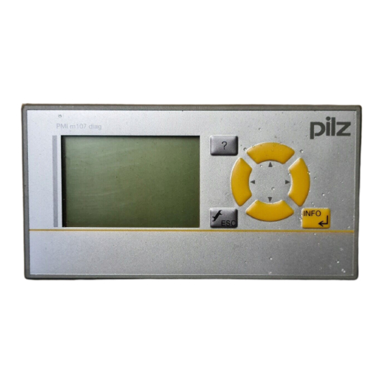
Unit Description Front view Fig. 4-1: Front view Display (see page 7-6) Help key 4 navigation keys Setup and <ESC> key <INFO> and <ENTER> key Key functions Description • Call up/close help for the current window • Call up main setup menu by holding the key down for 3 sec. •... -
Page 16: Side View, Including Interfaces
Unit Description Side view, including interfaces Fig. 4-2: Side view, including interfaces Supply voltage with polarity protection Threaded insert (M4) for the functional earth connection RS 232 interface RS 485 interface RS 485 interface termination Notice Please note the following during diagnostics on the PNOZmulti. The RS 232 interfaces on the PNOZmulti and PMImicro diag do not have galvanic isolation. -
Page 17: Side View, Including Cf Card Slot
Side view, including CF card slot Fig. 4-3: Side view, including CF card slot CF card slot (50-pin), side access Retaining clamp NOTICE Switch off the PMImicro diag before inserting or exchanging the CF card. Data on the CF card will be lost or the CF card itself may be damaged if you insert or exchange the CF card while the PMImicro diag is switched Inserting the CF card INFORMATION... -
Page 18: Interfaces
Unit Description • If you cannot fully insert the CF card, you may need to adjust the position of the CF card within the slot. • Do not force the CF card into the card slot. This will damage the CF card or the PMImicro diag. -
Page 19: Termination
Termination The RS 485 interface can be terminated internally (R 120 Ohm). Termination off Termination on Switch 4: on, Switch 4 ... 1: off Switch 3 ... 1: off Operating Manual: PMImicro diag... -
Page 20: Connection Diagram And Details Of Cables And Converters Pss/Safetybus P
Unit Description Connection diagram and details of cables and converters PSS/SafetyBUS p PSS/ CF card SafetyBUS p converter Description Order number RS 232 download cable 301960 RS 485 download cable 374205 RS 232 0 modem cable 301965 RS 232 0 modem cable PC - PSS 310300 RS 232/RS 485 interface converter 305159... -
Page 21: Connection Diagram And Details Of Cables And Converters Pnozmulti
Connection diagram and details of cables and converters PNOZmulti CF card PNOZmulti converter converter Description Order number RS 485 download cable 374205 RS 232 0 modem cable 301965 RS 232 0 modem cable PC - PSS 310300 RS 232/RS 485 interface converter 305159 Fig. - Page 22 Unit Description The PMImicro diag has 2 interfaces (1 x RS 232 and 1 x RS 485). These can be used for communication with either the connected device or the INFORMATION The interface may be configured either on the PMImicro diag or in the PMImicro Configurator.
-
Page 23: Installation And Wiring
Installation and Wiring Safety Please read the safety guidelines before assembling and installing the PMImicro diag. Before you install or commission the system, you should refer to any guidelines laid down by the plant manufacturer or operator. Installation site and unit surroundings •... -
Page 24: Nominal Dimensions
Installation and Wiring Nominal dimensions Mounting cut-out Fig. 5-1: Nominal dimensions, PMImicro diag Operating Manual: PMImicro diag... -
Page 25: Installing The Device
Installing the device When installing the unit, please note the following: • For reasons of stability, the front panel, console or control cabinet should have a wall thickness of at least 2.5 mm. • To avoid a build-up of heat, a distance of a 10 cm/3.94" should be maintained all round the system. -
Page 26: Connecting The Device
Installation and Wiring Connecting the device When connecting the PMImicro diag to the PC and to a device that supports expanded PVIS diagnostics, please refer to the connection dia- gram and the corresponding cable connection details (see page 4-6 ff). Supply voltage The 24 VDC supply voltage connection is on the side of the housing (see Fig. -
Page 27: Earth Connector
• Data lines and power lines should be laid separately to avoid capacitive and inductive transmission (recommended minimum distance = 10 cm/ 3.94"). • Screened data lines should also be laid in a different cable duct to the main power lines. •... -
Page 28: Screening
Installation and Wiring Screening • Connect the power cable screening with low impedance to earth. • Use screened data lines only. • Due to high frequency, we recommend that the screening on the data line cable (RS 232/RS 485 cable) is earthed on both sides. If you are using longer cables and there is the possibility of transient currents, we recommend one of the following methods: - use equipotential bonding cable... -
Page 29: Connection Example
Connection example 1: Earth star point 24 VDC on unit or control cabinet 2: Earth bus bar 3: Supply voltage 4: Earthing terminal (electronic) 5: Earthing bolt (housing) 6: Data line screening Fig. 5-5: Connection example Operating Manual: PMImicro diag... - Page 30 Installation and Wiring Notes Operating Manual: PMImicro diag...
-
Page 31: Commissioning
Commissioning General • Connect the supply voltage and the earth conductor (see page 5-4 ff). • For diagnostics, connect the PMImicro diag to a device with expanded diagnostic options PVIS. PSS/SafetyBUS p and PNOZmulti • To configure the PMImicro diag, connect the PMImicro diag to a PC. Please refer to the connection diagram and the corresponding cable connection details in Chapter 4 (see page 4-6 ff). -
Page 32: Default Setting
Commissioning INFORMATION If an error should occur while preparing for operation, a window will appear, showing an appropriate message. Default setting The procedure for commissioning the PMImicro diag is “plug and play”. The unit is supplied with the following default settings: •... - Page 33 • PNOZmulti vIO: Diagnostics for the virtual outputs on the PNOZmulti (German, English). You can choose between these devices/projects. (See interfaces, page 6-12) The selected configuration is copied to the project with which runtime is operating. This means that you can switch over or restore the default diagnostic configuration as often as you wish.
-
Page 34: Help
Commissioning Help Two types of help are available for the PMImicro diag: •Help on the PMImicro diag Call up help: press <?> Close help: press <?> or <ESC> key, also closes after timeout • Online help on the PMImicro Configurator The online help on the PMImicro Configurator can be found in the system software of the connected device. -
Page 35: Configuration
During operation you can make settings and poll information for the following menu items: • Log files Display, delete and export log files • Versions This is where you will find information on runtime, hardware, operating system etc. Configuration INFORMATION We recommend that you configure the user settings, for example, in the PMImicro Configurator on the connected device, as it easier to enter the data via the PC keyboard. - Page 36 Commissioning • Show delete information When an event is no longer present, the corresponding event message is deleted from the event list. If the event message or remedy is displayed at this point, the information „Message deleted“ can be displayed. •...
-
Page 37: General Guidelines On Operation
General guidelines on operation Display when window is opened Fig. 6-1: Display when window is opened The respective input field is selected when it is bordered by a dotted line (1). Press <ENTER>. This will access ... Display when input field is activated Fig. -
Page 38: Direction Of Selection In The Options List
Commissioning Direction of selection in the options list Fig. 6-3: Display when input field is activated Selection via the navigation keys can only be made in the direction of the arrows (3). • Select the required setting. • Press <ENTER> to accept the setting. •... -
Page 39: User Setting
7. The selection window for Config. is pre-selected. 8. Press <ENTER> and the selection window turns black. 9. Using the navigation keys, select ON/OFF . 10. Press <ENTER>. Your selection is saved. 11. Using the navigation keys, select the window for Log files . 12. -
Page 40: Select User
Commissioning Select user Proceed as follows: 1. Hold the <ESC> key down for three seconds. This will access the main menu. 2. Using the navigation keys, select Configuration . 3. Press <ENTER>. 4. Using the navigation keys, select User setting . 5. -
Page 41: Change User Name
Change user name Proceed as follows: 1. Select a user (see page 6-9). Fig. 6-5: Change user name 2. Press <ENTER>; the user name is selected and a cursor appears (1). The user name can be changed as follows: Replace character: Select the character using the navigation keys Select the new character using the navigation keys Delete character:... -
Page 42: Change Password
Commissioning 4. Press <ESC> to exit user name selection. 5. Press <ESC> to exit the menu. Change password Proceed as follows: 1. Select a user (see page 6-9). 2. Using the navigation keys, select Password. 3. Press <ENTER>. The password (2) becomes visible and can be changed. -
Page 43: Change Access Rights
Change access rights Proceed as follows: 1. Select a user (see page 6-9). Fig. 6-6: Change access rights 2. Using the navigation keys, select the access right (3). 3. Press <ENTER>; the access right can be changed. Two access rights can be assigned: 0: PMImicro configuration 1: Delete and export log files Example:... -
Page 44: Interfaces
Commissioning 5. Press <ESC> to exit access right selection. 6. Press <ESC> to exit the menu. Interfaces Configure the interfaces on the PMImicro diag: • for connection to the connected device • for connection to the PC The following settings may be made: •... -
Page 45: Select Connected Device
9. Press <ENTER>. Your selection is saved. A prompt appears, asking if you wish to restart the PMImicro diag. 10. Using the navigation keys, select YES . 11. Press <ENTER>. 12. The PMImicro diag is restarted. INFORMATION If you use the navigation keys to select NO under step 10, the unit will not be restarted. -
Page 46: Pc Interface
Commissioning 11. Press <ENTER>. 12. The PMImicro diag is restarted. INFORMATION If you use the navigation keys to select NO under step 10, the unit will not be restarted. You will need to restart the PMImicro diag later in order to activate the selection of the connected device. -
Page 47: Time Characteristics
Time characteristics Set the operator timeout and flash frequency . Operator timeout Once you have operated a key on the PMImicro diag, the PMImicro diag waits for the next entry. If this entry does not occur within the set Operator timeout , the display on the PMImicro diag will return to the highest-priority event message. -
Page 48: Flash Frequency
Commissioning Flash frequency Set the display’s flash frequency. Proceed as follows: 1. Hold the <ESC> key down for three seconds. This will access the main menu. 2. Using the navigation keys, select Configuration . 3. Press <ENTER>. 4. Using the navigation keys, select Time characteristics . 5. -
Page 49: System Time
System time Set the time and date, so that this data matches in the log files . Proceed as follows: 1. Hold the <ESC> key down for three seconds. This will access the main menu. 2. Using the navigation keys, select Configuration . 3. -
Page 50: Backup & Restore
Commissioning Backup & restore The backup & restore function enables you to save the PMImicro diag configuration, runtime and diagnostic configuration on to a CF card and, if necessary, to restore this information to the PMImicro diag or download it to other PMImicro diags. - Page 51 8. Using the navigation keys, select the window for the direction (-> CF card) . Data can then be written from the PMImicro diag to the CF card. 9. Press <ENTER>. 10. Using the navigation keys, select the window for Identifier . 11.
- Page 52 Commissioning Fig. 6-9: Backup; start download 16. Using the navigation keys, select Delete target (only possible from PMImicro diag -> CF card). The following options are available: Delete target selected: All data with the selected identifier is deleted before the information is copied to the CF card. Delete target deselected: Only selected data with the selected identifier, such as the PMImicro configuration, runtime and diagnostic configuration, is deleted before the information is copied to the CF card.
-
Page 53: (Save Data From Cf Card To Pmimicro Diag)
Restore (save data from CF card to PMImicro diag) NOTICE Switch off the PMImicro diag before inserting or exchanging the CF card. Data on the CF card will be lost or the CF card itself may be damaged if you insert or exchange the CF card while the PMImicro diag is switched Proceed as follows: 1. - Page 54 Commissioning 11. Press <ENTER> and the selection window turns black. 12. Using the navigation keys, set the required identifier. Only the identifiers for the files that are on the CF card are available. Fig. 6-11: Restore; select data 13. Press <ENTER>. 14.
- Page 55 16. Using the navigation keys, select Start . 17. Press <ENTER>. 18. A window appears with a prompt, asking if you wish to send the data. 19. Using the navigation keys, select Yes/No and then confirm your selection by pressing <ENTER>. YES: The data is downloaded.
-
Page 56: Integrity Display Pss/Safetybus P
Commissioning Integrity display PSS/SafetyBUS p A test is carried out to check that all the components for diagnostics are compatible. The diagnostic configuration on the connected device, the diagnostic configuration on the PMImicro diag and the program on the connected device must all be compatible in order for diagnostics to be performed correctly. -
Page 57: Project Name
Project name Shows the name of the following components (using a PSS as an example of a connected device): • FS (user program for the failsafe section of the PSS) • ST (user program for the standard section of the PSS) •... -
Page 58: Crc
Commissioning Displays the check sum of the following components: • PNOZ (program and diagnostic configuration in the PNOZmulti) • PMI (diagnostic configuration in the PMImicro diag) Project name Displays the name of the following components: • PNOZ (program and diagnostic configuration in the PNOZmulti) •... -
Page 59: Show Delete Information
Show delete information Select whether or not to show delete information. Proceed as follows: 1. Hold the <ESC> key down for three seconds. This will access the main menu. 2. Using the navigation keys, select Configuration . 3. Press <ENTER>. 4. -
Page 60: Max. Number Of Entries In The Event List
Commissioning 9. Press <ENTER>. Your selection is saved. A prompt appears, asking if you wish to restart the PMImicro diag. 10. Using the navigation keys, select YES . 11. Press <ENTER>. 12. The PMImicro diag is restarted. INFORMATION If you use the navigation keys to select NO under step 10, the unit will not be restarted. - Page 61 The following values can be selected: - Digit 1 (hundreds digit): 0 ... 1 - Digit 2 (tens digit): 0 ... 9 - Digit 3 (ones digit): 0 ... 9 8. Press <ENTER>. Your selection is saved. A prompt appears, asking if you wish to restart the PMImicro diag. 9.
-
Page 62: Language
Commissioning Language Menu language The menu language is the language in which the main menu on the PMImicro diag is displayed. INFORMATION The languages that are available for selection depend on the the languages that are loaded on the PMImicro diag. A maximum of two languages are possible. -
Page 63: Display Settings
Display settings To achieve optimum legibility, the screen must be adjusted to the respective working environment. Set the display’s contrast and backlighting. Proceed as follows: 1. Hold the <ESC> key down for three seconds. This will access the main menu. 2. - Page 64 Commissioning 10. Press <ENTER>. Your selection is saved. 11. Press <ESC> to exit the menu. 6-34 Operating Manual: PMImicro diag...
-
Page 65: Log Files
Log files The log file is a file in which events are stored, with time details. If the PMImicro configuration and the diagnostic configuration support multiple languages, the language may later be switched for viewing and exporting the log files. There are two log files on the PMImicro diag: •... - Page 66 Commissioning 9. Press <ENTER>. This accesses the first entry. If the entry is too long t to be displayed on one page, the entry will be continued on an additional page. 10. Press <ENTER>; this accesses the entry’s second page. 11.
-
Page 67: Diagnostic Log File
21. Using the navigation keys, set the required identifier. 22. Press <ENTER>. 23. Using the navigation keys, select Start . 24. Press <ENTER>. 25. A window appears with a prompt, asking if you wish to perform the action. 26. Using the navigation keys, select Yes/No and then confirm your selection by pressing <ENTER>. - Page 68 Commissioning Display The event messages are displayed in the diagnostic language that is currently selected, showing details of time and date. 9. Press <ENTER>. This accesses the most recent event message. 10. Press <ENTER>. This accesses the displayed event description: <<+>>...
-
Page 69: Versions
23. Using the navigation keys, select Start . 24. Press <ENTER>. 25. A window appears with a prompt, asking if you wish to perform the action. 26. Using the navigation keys, select Yes/No and then confirm your selection by pressing <ENTER>. YES: The event messages are exported. - Page 70 Commissioning Notes 6-40 Operating Manual: PMImicro diag...
-
Page 71: Operation
Operation Download data When downloading data, please refer to the connection diagram in Chapter 4 (see page 4-6 ff). When downloading data with a CF card, please refer to the guidelines in Chapter 4 (see page 4-3). NOTICE Switch off the PMImicro diag before inserting or exchanging the CF card. Data on the CF card will be lost or the CF card itself may be damaged if you insert or exchange the CF card while the PMImicro diag is switched Diagnostic configuration... -
Page 72: Log Files
Operation Log files Please refer to Chapter 6 for details of the log files (see page 6-30 ff). PMImicro diag log file This is where the start behaviour for the PMImicro diag is recorded, along with any errors that occur in the process. The log can be exported to a CF card. -
Page 73: Routing Function: Pc <-> Connected Device Via Pmimicro Diag
Routing function: PC <-> Connected device via PMImicro diag Data can be looped through transparently so that a connected PC can also access the connected device directly. When the data download starts, the PMImicro diag recognises that the data has to be passed on. It exits diagnostic mode and switches to routing mode. -
Page 74: Diagnostics Pss/Safetybus P And Pnozmulti
Operation Diagnostics PSS/SafetyBUS p and PNOZmulti Event messages are sent to the diagnostic terminal from the connected programmable safety system. The event message is evaluated in the diagnostic terminal. In most cases, the corresponding event message is displayed in accordance with the diagnostic configuration and is entered in the event list. -
Page 75: Pmimicro Configurator
Please familiarise yourself with the basics for diagnostic configuration before you create a diagnostic configuration. You can do this by reading the online help on the PSS WIN-PRO system software or the online help on the PNOZmulti Configurator (PNOZmulti). INFORMATION The language selected for the diagnostic language depends on the diagnostic configuration on the PMImicro diag. -
Page 76: Priorities
Operation Priorities The event messages are divided into three priority classes: Symbol “Error” priority class “Warning” priority class “Status information” priority class • Error This priority class contains event messages to which it is absolutely essential that the user reacts. These event messages provide information on the status of a technical device, in which one or more functions have failed or are adversely affected. -
Page 77: Event List
Location description The location description is a precise description of the position of the device with the stated equipment identifier and displayed parameters. When performing diagnostics on the PNOZmulti, the location description is displayed in addition to a description of the event/action, provided the user has entered this information. -
Page 78: Message Display
Operation Message display Description of event press press Description of action press Fig. 7-1: Message display Current position in event; X -> error text (e.g. error), 1 ... 8 -> description of action Priority class (e.g. error) Event message (e.g. first entry of five available entries in this priority class)/type size: 6 x 8 pixels (2.7 x 4.7 mm) Symbols for priority classes: only displayed when an entry is present, flashes until the entry is displayed. -
Page 79: Navigation Within An Event Message
Navigation within an event message The following diagram shows the navigation within an event message. Using the keys described (see page 4-1) you can access the display for the error message and the remedy/action. <ENTER> Error Error Page 2 Page 1 “X”... -
Page 80: Navigation Between Event Messages
Operation Navigation between event messages The following diagram shows the navigation between event messages. Using the keys described (see table on page 4-1) you can access the respective event message and the corresponding remedy/action. Event Event Event message 1 message 2 message 3 Page Page... -
Page 81: Deleting Event Message
Deleting event message The following diagram shows the event messages that are displayed when an event message is deleted from the PSS. Subsequent event messages move up automatically, the event messages are “shifted”. List of event messages before an event message is deleted Event message goes;... -
Page 82: Incoming Event Message
Operation Incoming event message If a new event message is added, it is entered in the event list according to its priority. Existing event messages in the event list are “shifted” accordingly. The corresponding priority class symbol will flash, the event message that is currently displayed will remain there. -
Page 83: Pnozmulti Diagnostics Via Virtual Outputs
PNOZmulti diagnostics via virtual outputs The connected PNOZmulti safety relay sends signals to the diagnostic terminal via the virtual outputs. A total of 24 virtual outputs are available. A virtual output can be used for a counter. A message text is assigned to each signal in the diagnostic terminal. -
Page 84: Schematic Representation, Using The Virtual Output Vo1 As An Example
Operation Schematic representation, using the virtual output VO1 as an example PNOZmulti Virtual Virtual input/VO output/VO 0... 23 0... 23 PMImicro diag mappingtable.xml Signal @text00 @text17 @text17 Language switching (example: English) Message file Message file en.xml de.xml lang.text Deutsch English lang.text Display Example... -
Page 85: Mappingtable.xml
*1 PNOZmulti The virtual outputs on the PNOZmulti are evaluated as signals from the PMImicro diag. 24 outputs (VO0 ... VO23) are available (see Counter, page 7-23). *2 Send signal The VO1 signal is transmitted to the PMImicro diag via the serial interface (see page 4-6). - Page 86 Operation Create diagnostics For this you will need: • PC to edit the XML files • CF card • CF card reader or adapter for CF card, order no.: 375300 Proceed as follows: 1. Copy the backup folder in the sample project on to your PC (see Fig. 7-6).
- Page 87 INFORMATION The directory structure must be maintained if the files are to be downloaded to the PMImicro diag using the restore function. Fig. 7-6: Configuration files, directory structure Operating Manual: PMImicro diag 7-17...
-
Page 88: Message Files
Operation mappingtable.xml The identification labels are assigned to the virtual outputs in the mappingtable.xml file. A total of 24 outputs (VO0 ... VO23) are available (see Counter, page 7-23). The mappingtable.xml file has the following structure: <?xml version=“1.0" encoding=“UTF-8" ?> - <configuration>... - Page 89 Message files The message texts are stored in a message file. The texts can be amended, added or deleted at any time. A separate message file must be created for each language. The identification labels are identical, but the texts are stored under the relevant language.
- Page 90 Operation The message file de.xml has the following structure: <?xml version=“1.0" encoding=“UTF-8" ?> - <configuration> <comment>Demo from 2005-10-17</comment> Freely available: e.g. project name, date, author etc. <key name=“languagetext“>Deutsch</key> Text for diagnostic language selection - <section name=“texts“> Special <key name=“@text_no_connection“>Keine Verbindung</key> <key name=“@text_no_run“>PNOZmulti ist in STOPP</key>...
- Page 91 INFORMATION Please note that a message text is limited to 10 lines of 20 characters. Depending on the wordwrap, a maximum of 200 characters may be displayed. You can write as many message texts as you like in the message files. INFORMATION If you add a new message text to a message file, please ensure that the message text is assigned to the corresponding identification label in the...
-
Page 92: Message Display
Operation Message display Fig. 7-9: Message display Number of messages currently present Direction of part counter (only when the part counter is switched on) Counter status, 5-digit display (only when the part counter is switched on) Message text with bullet point Scroll bar A maximum of 6 lines can be displayed. -
Page 93: Part Counter
Part counter The part counter can be used to count forwards and backwards. The part counter may be switched on and off. press Apply + Fig. 7-10: Part counter Function The counter pulse is triggered via virtual output VO23 on the PNOZmulti. If the part counter is switched off, a message text is assigned to virtual output VO23. -
Page 94: Configuration
Operation Configuration When configuring the part counter please refer to the guidelines given for the key functions (see page 4-5) plus the general guidelines on operation (see page 6-6). Part counter forwards Proceed as follows: 1. Press either of the two navigation keys: This will access the counter’s setup menu. -
Page 95: Pmimicro Configuration
Part counter switched off Proceed as follows: 1. Press either of the two navigation keys: This will access the counter’s setup menu. 2. Using the navigation keys, select the function that is selected. 3. Press <ENTER>. The option is deselected. 4. -
Page 96: Logbook
Operation Logbook The logbook function is not supported on PNOZmulti vIO diagnostics and is greyed out in the menu. Versions Display on the PNOZmulti: CRC and date 7-26 Operating Manual: PMImicro diag... -
Page 97: Technical Details
Technical Details Technical details Electrical data Supply voltage 12 ... 32 VDC Rated supply voltage 24 VDC Display Display type LC dot matrix graphic module Resolution 128 x 64 Bit Display range 60 x 40 mm (W x H) Backlighting White LEDs Interfaces Serial interfaces... -
Page 98: Technical Details
Technical Details Mechanical data Housing material Housing Stainless steel Front ABS Polyflam, UL listed Dimensions (with front panel) (H x W x D) 78 mm x 148 mm x 57 mm Modular depth 51 mm Weight 370 g Operating Manual: PMImicro diag... - Page 99 +49 711 3409-444 represented by our subsidiaries support@pilz.com and sales partners. Please refer to our homepage for further details or contact our headquarters. Pilz GmbH & Co. KG Felix-Wankel-Straße 2 73760 Ostfildern, Germany Telephone: +49 711 3409-0 Telefax: +49 711 3409-133 E-Mail: pilz.gmbh@pilz.de...
Need help?
Do you have a question about the PMI m107 diag and is the answer not in the manual?
Questions and answers
Pourquoi est-ce que c’est qui rouge ?