Table of Contents
Advertisement
Quick Links
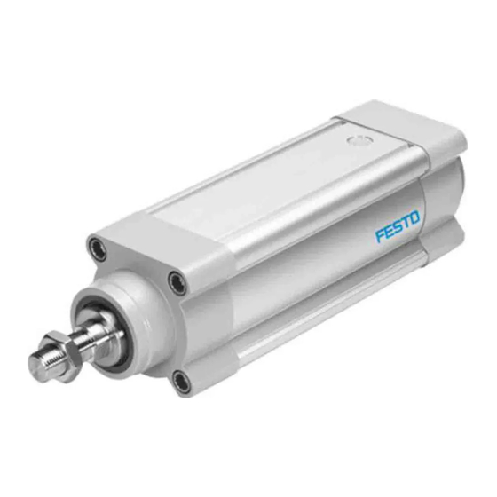
ESBF-BS, ESBF-LS
Electric cylinder
Instructions | Operating
8111672
201906c
[8111674]
Translation of the original instructions
© 2020 all rights reserved to Festo SE & Co. KG
1
Applicable documents
All available documents for the product è www.festo.com/pk.
2
2.1
Safety instructions
–
Observe labelling on the product.
–
Prior to assembly, installation and maintenance work: Switch off power sup
ply, ensure that it is off and secure it against being switched back on.
–
Store the product in a cool, dry, UVprotected and corrosionprotected envir
onment. Ensure that storage times are kept to a minimum.
–
Observe tightening torques. Unless otherwise specified, the tolerance
is ± 20 %.
2.2
Intended Use
The electric cylinder is intended to be used for positioning payloads in combina
tion with tools or as a drive when external guides are used.
2.3
Training of qualified personnel
Installation, commissioning, maintenance and disassembly should only be con
ducted by qualified personnel. The qualified personnel must be familiar with
installation of electrical control systems.
3
Further information
–
Accessories è www.festo.com/catalogue.
–
Spare parts è www.festo.com/spareparts.
4
Service
Contact your regional Festo contact person if you have technical questions
è www.festo.com.
5
Product overview
5.1
Function
The electric cylinder converts the rotary motion of the mounted motor into a linear
motion of the nonrotating piston rod. The lead screw converts the torque of the
motor into a feed force. The linear movement of the piston rod is precisely guided
by the guide in the bearing cap. Sensors enable the monitoring of end positions,
reference position and intermediate position.
Lead screw ESBF-LS
–
Low speeds
–
Selfbraking with deenergised motor
(without brake)
Tab. 1 Overview of Lead Screw
Festo SE & Co. KG
Ruiter Straße 82
73734 Esslingen
Germany
+49 711 3470
www.festo.com
8111672
Ball screw drive ESBF-BS
–
High speeds
–
High forces
5.2
Product Design
Product Design ESBF
1 Piston rod
2 Threaded hole for mounting
3 Bearing cap
4 Cylinder profile
Fig. 1 Product structure ESBF (example ESBFBS)
6
Transport and Storage
NOTICE!
Unexpected and unbraked movement of components
•
Secure moving components for transport.
Transport and Storage Conditions
–
Take product weight into account è 14 Technical data.
Weight > 25 kg: transport with a suitable hoist (crossbrace) or with two per
sons.
–
Take the product focus into consideration.
–
Store and transport the product in its original packaging.
–
Store product in a cool, dry, shaded and corrosion protected environment.
–
Store product in ambient conditions without oils, greases and degreasing
vapours.
–
Ensure short storage times.
7
Mounting
7.1
Safety
WARNING!
Risk of Injury due to Unexpected Movement of Components
For vertical or slanted mounting position: when power is off, moving parts can
travel or fall uncontrolled into the lower end position.
•
Bring moving parts of the product into a safe end position or secure them
against falling.
7.2
Unpacking
1. Open the packaging.
2. Remove all transport materials (e.g. foils, caps, cardboard boxes).
3. Remove the product from the packaging and place it on the mounting surface.
4. Dispose of packaging and transport materials è 13 Disposal.
7.3
Mounting the Motor
Lateral Force on the Drive Shaft
When mounting the motor and motor mounting kit, do not exceed the max. lateral
force Fq of the drive shaft (for example toothed belt tension when mounting the
parallel kit) è 14.2 Characteristic Curves.
Fig. 2 Motor mounting
Requirement
–
Only loosen screws or threaded pins that are described in the directions in
the instruction manual.
–
Provide sufficient space for connecting the pressure compensation
è Connecting Pressure Compensation (ESBF ... S1 only).
5 Pressure compensation opening
6 Drive cover
7 Drive shaft
8 Threaded hole for motor mounting
kit
Advertisement
Table of Contents

Related Manuals for Festo ESBF Series


Summary of Contents for Festo ESBF Series
- Page 1 4 Cylinder profile 8 Threaded hole for motor mounting Translation of the original instructions Fig. 1 Product structure ESBF (example ESBFBS) © 2020 all rights reserved to Festo SE & Co. KG Transport and Storage NOTICE! Applicable documents Unexpected and unbraked movement of components •...
- Page 2 When using other motors: observe the critical limits for forces, torques and velocities. Torque on the Piston Rod 2. Fasten motor mounting kit, observe instructions è www.festo.com/sp. During commissioning and operation, the piston rod may only be operated 3. Fasten the motor without tension. Support large and heavy motors.
- Page 3 Swinging up of the entire system – Query of end positions or intermediate positions. Recommendation: Reduce high force peaks in the acceleration and deceleration 1. Select accessories è www.festo.com/catalogue. phases by using the jerk limitation. 2. Mount the sensor (reference or query): –...
- Page 4 Roller bearing grease Roller bearing grease, LUBKC1 suitable for use in the – Send the electric cylinder to the Festo repair service. food industry LUBE1 – Information about spare parts and accessories è www.festo.com/spareparts. Tab. 12 Overview of Lubrication Intervals and Accessories...
- Page 5 1.34 0.16 0.67 1.34 Max. acceleration [m/s For sizing of the electric cylinder, use the PositionDrives engineering software Repetition accuracy [mm] ±0.01 è www.festo.com/sp. Feed constant [mm/re ESBF-BS-32/40 Duty cycle Size Relative humidity 0 … 95 (noncondensing) Spindle pitch ...P Ambient temperature [°C] 0 … +60...
- Page 6 ESBF-...-63/80/100 ESBF-BS ESBF-LS Size 100 32 Weight Basic weight with 0 mm [kg] 0.78 1.24 1.98 3.17 7.39 11.1 0.67 1.08 1.72 stroke Additional weight per [kg] 15.5 19.3 1000 mm stroke Tab. 18 Materials and weight 14.2 Characteristic Curves ESBFBS63 ESBFBS100 Lateral Force Piston Rod ESBF -...
- Page 7 ESBFBS32 ... 5P/10P ESBFBS63...5P ESBFBS63...25P Fig. 19 ESBFBS32, pressure force F as a function of the piston rod length l ESBFBS63...10P Fig. 14 ESBFBS63, feed force F as a function of the feed speed v ESBFBS40 ... 5P/10P ESBFBS40...16P Fig. 20 ESBFBS40, pressure force F as a function of the piston rod length l ESBFBS80...5P ESBFBS80...32P ESBFBS80...15P...
- Page 8 ESBF-63 1000 1200 l [mm] ESBFBS63...5P ESBFBS63...25P ESBFLS32…2.5P ESBFLS50...4P ESBFBS63...10P ESBFLS40…3P Fig. 30 ESBFBS63, feed speed v as a function of the stroke l Fig. 25 ESBFLS32/40/50, pressure force F as a function of the piston rod length l ESBF-80 Feed Speed – Stroke ESBF-BS Max. feed speed v as a function of the stroke l Fig.
Need help?
Do you have a question about the ESBF Series and is the answer not in the manual?
Questions and answers