
Related Manuals for Airspan AirSpeed 1050 B3


Summary of Contents for Airspan AirSpeed 1050 B3
- Page 1 AirSpeed 1050 B3 Installation Guide Part Number: DUG01593 System Release: 16.5 Revision: A Published: December 2020...
- Page 2 Airspan Networks Inc. reserves the right, without prior notice or liability, to make changes in equipment design or specifications. Information supplied by Airspan Networks Ltd. is believed in good faith to be accurate and reliable, while every care has been taken in preparing these documents.
-
Page 3: Table Of Contents
DECLARATION OF CONFORMITY............... 7 GPS Compliance ....................9 Maximum Output TX Total Power ............10 Power Consumption ..................... 10 Product Variants ....................10 Antenna System ....................11 About This Document ................12 Purpose ........................ 12 DUG01593 Airspan Commercial and Internal Use... - Page 4 2.1 Verify the Tools ..................... 16 2.2 Verify the Parts and Kits ................16 3 Physical Description ................18 3.1 AirSpeed 1050 B3 Physical Dimensions ............18 3.2 Bottom View ....................19 3.3 Power… ......................19 3.3.1 Environmental ....................19 3.4 LEDs Display ....................
- Page 5 Figure 6: Mounting Adaptor Assembly ....................22 Figure 7: Securing on Mounting Bracket ....................23 Figure 8: AirSpeed 1050 B3 on Pole Mounting Arm (example) ............23 Figure 9: Ground Connection ........................ 24 Figure 10: Stripping Dimensions (AC Cable) ..................25 Figure 11: Open Housing Lock ......................
- Page 6 Figure 53: Secure Housing Lock ......................37 Figure 54: Removal from the Mounting Arm ..................39 Tables Table 1: AirSpeed 1050 B3 FCC Maximum Output Total Power............10 Table 2: Power Consumption ........................ 10 Table 3: Variants ........................... 10 Table 4. Tool Requirements - Mounting ....................16 Table 5: AirSpeed 1050 B3 Components .....................
- Page 7 AirSpeed 1050 B3 Installation Guide Table 13. Tool Requirements - Removal ....................38 DUG01593 Airspan Commercial and Internal Use...
-
Page 8: Document Information
AirSpeed 1050 B3 Installation guide Document Information This document details procedures for installing the Airspan’s AirSpeed 1050 B3 Pico-class LTE eNodeB variant. Document Approvals Department Name Role Approval date Product Management Product Line Manager R&D Digital HW Group Manager Revision History... -
Page 9: Warnings And Cautions
AirSpeed 1050 B3 Installation Guide Warnings and Cautions Human Exposure to Radio Frequencies The AirSpeed 1050 B3 when operational should be operated from a minimum safe distance of 2.09ft (64cm). Avertissement et Precautions d’Utilisation Exposition des personnes aux fréquences radioélectriques Les antennes d’AirSpeed 1050 B3 quand opérationnel doivent être installée et utilisée de façon à... -
Page 10: Général
Toute enfreinte a ces obligations peut annuler la garantie délivrée par Airspan pour ces produits et peut exposer l’utilisateur final ou le fournisseur de services a des dommages légaux et financiers. -
Page 11: Securite
Substances Hazardous to Health Regulations 1989 and the Dangerous Substances Regulations 1990). At the end of any Airspan products life cycle, the customer should consult with Airspan to ensure that the product is disposed of in conformance with the relevant regulatory requirements. -
Page 12: Attention Aux Voltages Hasardeux
Airspan equipment is compliant with CE and R&TTE regulations and can be operated in all EU (European Union) locations listed below:... -
Page 13: Ul Information
- AirSpeed 1050 B3 is designed to operate in environmental conditions complying with IP66 and relevant standards. -
Page 14: Outdoor Cabling
This equipment is in compliance with the essential requirements and other relevant provisions of Directive 2014/53/EU. Español: Por medio de este Airspan, declara que la unidad cumple con los requisitos esenciales y cualquier otra disposición aplicable o exigible de la Directiva 2014/53 / UE. Greek: ΜΕ... - Page 15 2014/53 / EU. Íslenska: Airspan lýsir hér með yfir að þessi eining uppfylli grunnkröfur og aðrar kröfur tilskipunar 2014/53 / ESB. Norsk: Airspan erklærer herved at utstyrsenheten oppfyller grunnleggende krav og andre relevante krav i direktiv 2014/53 / EU.
-
Page 16: Gps Compliance
Note: A GPS is recommended for synchronizing the unit (included in the system). Note: An optional GPS Lightning/Surge protector is available from Airspan when installing the GPS antenna in a remote location for lightning prone deployments. DUG01593 Airspan Commercial and Internal Use... -
Page 17: Maximum Output Tx Total Power
1050 Caution: Do not set maximum output TX power to higher than local regulations. Power Consumption AirSpeed 1050 B3 power consumption is described in the following table: Table 2: Power Consumption Tx Power at RF Port Nominal Power Consumption Max Power Consumption... -
Page 18: Antenna System
AirSpeed 1050 B3 Installation Guide Antenna System The AirSpeed 1050 B3 includes embedded antennas: 2x SBA. Each SBA includes two antenna elements which can be switch on/off. Figure 1: AirSpeed 1050 B3 DUG01593 Airspan Commercial and Internal Use... -
Page 19: About This Document
Connect and manage cables Intended Audience This guide is intended for persons who are responsible for installing the AirSpeed 1050 B3 equipment. These persons should have a working knowledge of the equipment. Related Reading The following documents contain related information: ... -
Page 20: Customer Care Help Desk
Customer Care Help Desk Airspan’s Customer Care Help Desk offers prompt and efficient customer support services. To avail Airspan’s Customer Care Help Desk support, you must be a registered user and must Note: have a valid support contract. To register, click here and fill the Registration form. -
Page 21: Introduction
This section provides a descriptive overview of the Airspan’s AirSpeed 1050 B3 variant(s) and its place in the Airspan product suite. AirSpeed 1050 B3 is a standalone product with fiber and copper backhaul. It includes dual sector access with SBA antenna. The product is aimed for outdoor deployment, on a pole top or side as well as wall mounting. -
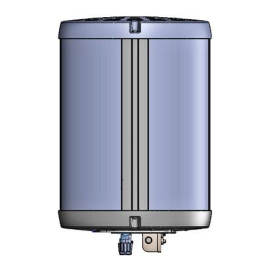
Page 22: Figure 2: Airspeed 1050 B3
AirSpeed 1050 B3 Installation Guide Figure 2: AirSpeed 1050 B3 Note: The illustration above displays the AirSpeed 1050 B3 unit (with mounting adaptor). DUG01593 Airspan Commercial and Internal Use... -
Page 23: Verifying Prerequisites
AirSpeed 1050 B3 Installation Guide 2 Verifying Prerequisites Prior to installing the AirSpeed 1050 B3, verify the required safety, power, tools, parts and components. This chapter includes the hardware, software, and client requirements for installation. Verify the availability of: ... - Page 24 AirSpeed 1050 B3 Installation Guide Installation Kit / Part Product Code AS P/N Description OCTIS Connector Adapter Connector Adapter CON-ADP-OCT-SFP-1 10135746 SFP (ordered separately) ETH - RJ45 connector ,Right (R) pitch Connector Adapter CON-ADP-OCT-RJ45-1 300-20-062 (ordered separately) RJ45 26mm DUG01593...
-
Page 25: Physical Description
AirSpeed 1050 B3 Installation Guide 3 Physical Description AirSpeed 1050 B3 is in an all outdoor enclosure. This section provides the physical attributes of the AirSpeed 1050 B3. Figure 3: AirSpeed 1050 B3 Overall Dimensions 3.1 AirSpeed 1050 B3 Physical Dimensions Table 6. -
Page 26: Bottom View
AC - 90~240 VAC, 50-60Hz 3.3.1 Environmental Note: AirSpeed 1050 B3 is not meant to be used in a Marine environment. AirSpeed 1050 B3 meets the following environmental requirements: GR-63 Storage and Transportation ETSI EN 300-019-1-4 Operational (non-weather protected equipment) ... -
Page 27: Leds Display
AirSpeed 1050 B3 Installation Guide Table 8. AirSpeed 1050 B3 Environment Compliance Type Details -40°C to 55°C / -40°F to 131°F Operating temperature Operating humidity 5% - 100% non-condensing Storage temperature -40°C to 70° C / -40°F to 158°F Rain and dust ingress protection IP66 3.4 LEDs Display... -
Page 28: Installation Of Airspeed 1050 B3
AirSpeed 1050 B3 Installation Guide 4 Installation of AirSpeed 1050 B3 AirSpeed 1050 B3 is installed on a pole. Prior to installation of the AirSpeed unit a mounting arm (not supplied) must first be affixed in place on the Pole. -
Page 29: Mounting Adaptor Assembly
Using a #5 Allen wrench, tighten to a torque of no more than 5.2 Nm (46.02 in-lbs.) max. 4.2 Mounting The following images show the assembly of the AirSpeed 1050 B3 onto the pole mounting arm (not supplied, responsibility of the installer). -
Page 30: Figure 7: Securing On Mounting Bracket
Using higher than specified tightening torque might damage the unit or mounting arm. Note: Use an appropriate wrench only and tighten with caution so as not to cause damage to the paint. Figure 8: AirSpeed 1050 B3 on Pole Mounting Arm (example) DUG01593 Airspan Commercial and Internal Use... -
Page 31: Connect And Manage Cables
4.4 TX Power Monitoring Port There is the option to monitor TX power via the available monitoring ports (SMA Jack B/H) found on the bottom of the AirSpeed 1050 B3 unit. See Figure 4: AirSpeed 1050 B3 Bottom. 4.5 Cable Connection The following explains the general instructions on how to connect a power cable (AC) and the SFP &... -
Page 32: Ac Cable Preparation
AirSpeed 1050 B3 Installation Guide Tip: It is good practice to label both ends of the cable to identify which AirSpeed 1050 B3 unit it is connected to. Tip: It is good practice to leave a spare loop of cable (approximately 0.5m). This will allow for easier wiring and will allow the cable to be re-terminated if necessary in the future. -
Page 33: Figure 12: Seperate Into Sections
AirSpeed 1050 B3 Installation Guide Separate the housing into its component sections. Figure 12: Seperate into Sections Insert the Gland nut through the other end of the cable. Figure 13: Insert Gland Nut Feed the end of the source power cable through the housing of the AC connector. -
Page 34: Figure 15: Insert Wire To Housing
AirSpeed 1050 B3 Installation Guide Figure 15: Insert Wire to Housing Verify the wires are in their correct stations. Figure 16: AC Wire Placement Table 11: Wire Pinout Connection Position # Ground Line Neutral Tighten the three (3) set screws as shown below. -
Page 35: Figure 18: Cable Click In Place
AirSpeed 1050 B3 Installation Guide Figure 18: Cable Click in Place 10. Place the split rubber gland onto the cable. Figure 19: Place Split Rubber Gland 11. Verify the gland size as shown below. Table 12: Recommended Gland Sizes Cable Diameter Recommended Gland Size “Φ8”... -
Page 36: Figure 21: Place Tightening Cone On Split Gland
AirSpeed 1050 B3 Installation Guide Figure 21: Place Tightening Cone on Split Gland 13. Secure the Gland nut on to the body forcing the seal to compress around the power cable, then tighten the Gland nut with a 21mm wrench. -
Page 37: Fiber Ethernet (Sfp) Cable Preparation
AirSpeed 1050 B3 Installation Guide Note: After locking the secondary lock/button and lever, it is required to fasten down the lever mechanism with the supplied metal/plastic tie (to prevent easy opening) and verify that it is secure, as shown below. -
Page 38: Figure 28: Open Housing Lock
AirSpeed 1050 B3 Installation Guide Figure 28: Open Housing Lock Separate the housing into its component sections. Insert the gland nut through the front end of LC Duplex assembly. Figure 29: Gland Nut on Cable Insert the “split tightening cone” from the side of the cable. -
Page 39: Figure 32: Pass Cable Thru Housing
AirSpeed 1050 B3 Installation Guide Figure 32: Pass Cable thru Housing Insert the LC Duplex cable into the transceiver. A “click” is heard when engaged. Figure 33: Insert Cable into Transceiver Insert the holder subset section from the front end of Transceiver. -
Page 40: Figure 36: Holder Into Transceiver
AirSpeed 1050 B3 Installation Guide Figure 36: Holder into Transceiver 11. Lift the lever of housing base slightly so that the rubber gland, tightening cone and gland nut can be inserted and tightened correctly. Figure 37: Lift Lever 12. Push to insert the rubber gland. -
Page 41: Copper Ethernet Cable Preparation
AirSpeed 1050 B3 Installation Guide Figure 40: Tighten Gland Nut 15. Secure the lock by sliding the secondary lock/button, so that lever can’t be lifted; assembly is now ready for insertion. Figure 41: Secure Housing Lock 4.5.3 Copper Ethernet Cable Preparation Note: A pre-assembled RJ45 cable is required for the Copper Ethernet assembly. -
Page 42: Figure 44: Insert Tightening Cone On Cable
AirSpeed 1050 B3 Installation Guide For recommended gland size see Table 12: Recommended Gland Size Figure 44: Insert Tightening Cone on Cable Insert the “split rubber gland” from side of the cable. Note: Inner diameter of rubber gland is in the range of 7 to 8mm (0.28-0.31) range. -
Page 43: Figure 48: Holder Into Housing Base
AirSpeed 1050 B3 Installation Guide Figure 48: Holder into Housing Base Ensure correct alignment of the RJ45 in the hosing by raising the lever to allow free movement and then push the RJ45 plug into the plug cap to ensure proper location, then lock the cap. -
Page 44: Figure 52: Tighten Gland Nut
AirSpeed 1050 B3 Installation Guide Figure 52: Tighten Gland Nut 12. Close the lever and secure the lock by sliding the secondary lock/button, so that lever can’t be lifted; assembly is now ready for insertion. Figure 53: Secure Housing Lock... -
Page 45: Removal Of Airspeed 1050 B3
AirSpeed 1050 B3 Installation Guide 5 Removal of AirSpeed 1050 B3 The following steps define removal procedure for the AirSpeed 1050 when required (for replacement). 5.1 Tool Requirements The following defines the tools required for safe removal of the AirSpeed unit. -
Page 46: Airspeed Removal From The Pole Mounting Arm
AirSpeed 1050 B3 Installation Guide 3. Take all the bundled cables and temporarily fasten them to the mounting arm using the electrical tape so they do not hang loose. The cables will be required and accessible to reconnect the new unit. -
Page 47: A Job Sheet
AirSpeed 1050 B3 Installation Guide A Job Sheet This job sheet enables the users to keep track of their installation. It covers all the prerequisites required for accomplishing the AirSpeed 1050 B3 installation. Site Requirements Installation location identified Access restrictions (highway regulations, other services on pole, power... -
Page 48: B Abbreviations
AirSpeed 1050 B3 Installation Guide B Abbreviations Term Definition Alternating Current Backhaul Direct Current eNodeB Ethernet (cable) Frequency Division Duplex File Transfer Protocol Long Term Evolution, marketed as “4G LTE”, is a standard for wireless communication of high-speed data for mobile phones...
Need help?
Do you have a question about the AirSpeed 1050 B3 and is the answer not in the manual?
Questions and answers