
Subscribe to Our Youtube Channel
Related Manuals for Airspan AirHarmony-4400


Summary of Contents for Airspan AirHarmony-4400
- Page 1 AirHarmony-4400 Installation Guide External Cavity Filters Part Number: UGD-D01186 System Release: 15.0 Revision: A Published: December 2016...
- Page 2 Airspan Networks Ltd. reserves the right, without prior notice or liability, to make changes in equipment design or specifications. Information supplied by Airspan Networks Ltd. is believed in good faith to be accurate and reliable, while every care has been taken in preparing these documents. However, Airspan Networks Ltd. does not make any representations and gives no warranties of whatever nature in respect of these documents, including without limitation, the accuracy or completeness of any information, facts and/or opinions contained therein.
-
Page 3: Table Of Contents
DECLARATION OF CONFORMITY ................... 8 GPS Compliance ........................9 Maximum Output TX Total Power ..............9 Power Consumption ......................10 Antenna System ........................10 Long Switched Beam Antenna .................... 10 External Antenna ......................... 11 UGD-D01186 Airspan Commercial and Internal Use... - Page 4 AirHarmony-4400 (External Cavity Filters) Installation Guide About This Document ..................12 Purpose ..........................12 Intended Audience ......................12 Document Conventions ....................... 12 Document Organization ...................... 13 Related Reading ........................13 Customer Care Help Desk ................14 Airspan Encourages Comments ..................14 1 Introduction ....................
- Page 5 Figure 4: AirHarmony-4400 Unit, Bottom panel ................... 22 Figure 5: AirHarmony-4400 Unit, Top panel ..................23 Figure 6: AIrHarmony-4400 - in Horizontal Position prior to Rear External Filters Set Assembly ..25 Figure 7: Rear External Filters' Set ......................26 Figure 8: Mounting Rear External Filters' set ..................
- Page 6 Table 2: AirHarmony-4400DH B41 High Band FCC Maximum Output TX Total Power ......9 Table 3: AirHarmony-4400DL B41 Low Band FCC Maximum Output TX Total Power ......10 Table 4: AirHarmony-4400 ETSI Maximum Output TX Total Power ............. 10 Table 5: Power Consumption ........................ 10...
- Page 7 Table 7. Minimum Hardware Requirements ..................18 Table 8. Parts & Kits ..........................19 Table 9. Amperage Draw........................22 Table 10: AirHarmony-4400 Physical Dimensions ................23 Table 11: AirHarmony-4400 Environment Compliance ................ 24 Table 12: Job Sheet ..........................54 UGD-D01186...
-
Page 8: Document Information
Document Information Abstract This document details procedures for installing the Airspan’s AirHarmony-4400 EXT, a Macro-class eNodeB variant and its place in the Airspan product suite. This document is intended for qualified personnel with a working knowledge of LTE. Revision History... -
Page 9: Warnings And Cautions
Connect the equipment to a circuit different from that to which the power source is connected Modifications Any changes and modifications to this device that are not expressly approved by Airspan Networks may void the user's authority to operate the equipment. General ... -
Page 10: Important Safety Instructions
Toute enfreinte a ces obligations peut annuler la garantie délivrée par Airspan pour ces produits et peut exposer l’utilisateur final ou le fournisseur de services a des dommages légaux et financiers. -
Page 11: Securite
Substances Hazardous to Health Regulations 1989 and the Dangerous Substances Regulations 1990). At the end of any Airspan products life cycle, the customer should consult with Airspan to ensure that the product is disposed of in conformance with the relevant regulatory requirements. -
Page 12: Adherence To European Directive 1999/5/Ec
Airspan equipment is compliant with CE and R&TTE regulations and can be operated in all EU (European Union) locations listed below:... -
Page 13: Ul Information
- AirHarmony-4400 is designed to operate in environmental conditions complying with IP66 and relevant standards. -
Page 14: Outdoor Ethernet Cabling
Español: Este equipo cumple con los requisitos esenciales asi como con otras disposiciones de la Directive 1999/5/EC. Greek: ΜΕ ΤΗΝ ΠΑΡΟΥΣΑ Airspan ΔΗΛΩΝΕΙ ΟΤΙ Ο ΕΞΟΠΛΙΣΜΟΣ ΣΥΜΜΟΡΦΩΝΕΤΑΙ ΠΡΟΣ ΤΙΣ ΟΥΣΙΩΔΕΙΣ ΑΠΑΙΤΗΣΕΙΣ ΚΑΙ ΤΙΣ ΛΟΙΠΕΣ ΣΧΕΤΙΚΕΣ ΔΙΑΤΑΞΕΙΣ ΤΗΣ ΟΔΗΓΙΑΣ 1999/5/ΕΚ. Français: Cet appareil est conforme aux exigencies essentialles et aux autres dispositions pertinantes de la Directive 1999/5/EC. -
Page 15: Gps Compliance
Note: A GPS is recommended for synchronizing between LTE sectors. Note: An optional GPS Lightning/Surge protector is available from Airspan when installing the GPS antenna in a remote location for lightning prone deployments. Maximum Output TX Total Power Table 1: AirHarmony-4400DF B41 Full Band FCC Maximum Output TX Total Power... -
Page 16: Power Consumption
2 x 43 Antenna System AirHarmony-4400 comes in a range of frequency variants that can be mounted with different antenna options and formats. A typical installation will have a cross-polar sector or dual slant antenna connected to the approprate Cavity filter of the AirHarmony-4400 variant unit. Various antennas are designed specifically for AirHarmony-4400 deployments;... -
Page 17: External Antenna
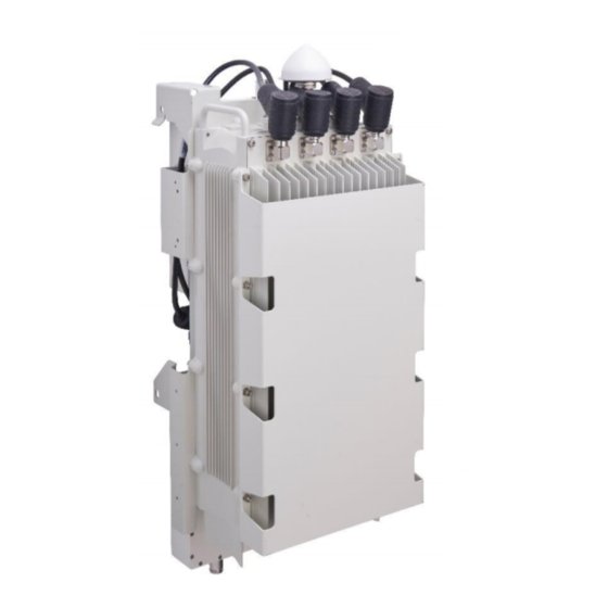
Note: When utilized in conjunction with iRelay as backhaul maintain a vertical separation of at least 2 ft. (0.6 m). Figure 1: AirHarmony-4400 with external cavity filters & cover UGD-D01186 Airspan Commercial and Internal Use... -
Page 18: About This Document
Connect and manage cables Intended Audience This guide is intended for persons who are responsible for installing the AirHarmony-4400. These persons should have a working knowledge of the equipment. AirHarmony can be tightly integrated with Airspan’s iBridge and iRelay transport solutions. -
Page 19: Document Organization
Note Provides additional information. Provides helpful hints. Document Organization Chapter Contents Provides a comprehensive overview of AirHarmony-4400 and its Introduction installation. Getting Started Provides workflows for initial install and workflow. Lists the hardware, software, and client requirements for Verifying Prerequisites installation. -
Page 20: Customer Care Help Desk
Customer Care Help Desk Airspan’s Customer Care Help Desk offers prompt and efficient customer support services. Note: To avail Airspan’s Customer Care Help Desk support, you must be a registered user and must have a valid support contract. To register, click here and fill the Registration form. -
Page 21: Introduction
4T4R, 4T8R, and 8T8R. AirHarmony-4400 implements 2 x 20W transmitters (2 x 43 dBm) and fully supports the standard LTE (Uu/S1/X2) interfaces. All Airspan eNodeB products, including AirHarmony-4400, are interoperable with a rich portfolio of party end user devices, including many handsets, indoor UEs, outdoor UEs and USB dongles from several ODMs, using various chipsets. -
Page 22: Figure 2: Airharmony-4400 With Front & Rear Filter Sets & Cover
AirHarmony-4400 (External Cavity Filters) Installation Guide Note: AirHarmony-4400 must be properly grounded (16AWG minimum) according with NEC and other local safety code requirements. Warning: Required - circuit breaker for AC power source -16A for EU installation and 20A for US installation. -
Page 23: Getting Started
AirHarmony-4400 (External Cavity Filters) Installation Guide Getting Started 2.1 Workflow of Installation The Workflow to install the AirHarmony-4400 is displayed in the following diagram: Figure 3: Workflow Caution: Antennas and External filters must be connected and attached before AirHarmony-4400 is powered on. -
Page 24: Airharmony-4400 Installation Checklist
AirHarmony-4400 (External Cavity Filters) Installation Guide 2.2 AirHarmony-4400 Installation Checklist Plan the installation of the AirHarmony-4400 by using the Installation Checklist, which you can find as a removable job aid in Appendix A for this guide. 3 Verifying Prerequisites Prior to installing the AirHarmony-4400, verify the required safety, power, tools, parts and components. -
Page 25: Verify The Parts And Kits
AirHarmony-4400 (External Cavity Filters) Installation Guide 3.2.2 Verify the Parts and Kits Note: Verify your order and requirements to ensure the correct unit type is being installed. Table 8. Parts & Kits Installation Part No. Airspan Consisting of: Image Kit / Part... - Page 26 AirHarmony-4400 (External Cavity Filters) Installation Guide Installation Part No. Airspan Consisting of: Image Kit / Part LSBA Control Cable Long SBA CBL- 680-00-191 control cable SBAL- AISG to AISG CTRL- 1.5m 1.5-1 Long SBA CBL- 680-00-192 control cable SBAL- AISG to AISG...
-
Page 27: Power Supply And Current
SM-1 Outdoor LC/DPX to LC, IP67 3.2.3 Power Supply and Current AirHarmony-4400 supports direct connection to AC power source: Operational Voltage Range: 100VAC~240VAC, 47Hz~63Hz Warning: Power provided by PoE outputs (RJ45 ETH1, ETH2) cannot be considered limited power source (LPS) per IEC/UL 60950-1 clause 2.5... -
Page 28: Panels
Maximum Power Consumption (W) TDD-FC1 2 x 43 2 x 43 3.2.4 Panels The following figures display the AirHarmony-4400 bottom and top panels. The following displays the AirHarmony-4400’s bottom panel. Figure 4: AirHarmony-4400 Unit, Bottom panel UGD-D01186 Airspan Commercial and Internal Use... -
Page 29: Physical Dimensions
AirHarmony-4400 (External Cavity Filters) Installation Guide The following displays the AirHarmony-4400’s top panel. Figure 5: AirHarmony-4400 Unit, Top panel 3.2.5 Physical Dimensions AirHarmony-4400 is in an all outdoor enclosure. Table 10: AirHarmony-4400 Physical Dimensions Variant Dimensions (H x W x D) AirHarmony-4400 509 x 262 x 252 mm / 20.0 x 10.3 x 9.9 inch... -
Page 30: Environmental
AirHarmony-4400 (External Cavity Filters) Installation Guide 3.2.6 Environmental AirHarmony-4400 meets the following environmental requirements: GR-63 Storage and Transportation ETSI EN 300-019-1-4 Operational (non-weather protected equipment) ETSI EN 300-019-1-1 Storage (weather protected, non-temperature controlled locations) ETSI EN 300-019-1-2 Transportation... -
Page 31: Installing Airharmony-4400
AirHarmony-4400 (External Cavity Filters) Installation Guide 4 Installing AirHarmony-4400 Install the AirHarmony-4400 eNodeB by pole/wall mount. AirHarmony-4400 is mounted on a pole or wall in close proximity to its external antenna (connectorized variant). Caution: Proper local rigging and hoisting practices should be followed when installing the AirHarmony-4400 on pole or wall. -
Page 32: Figure 7: Rear External Filters' Set
Align the four screw slots in order to fit the rear external filters’ set in place. Position the rear external filters’ set on the AirHarmony-4400 in position so the slots on the sides align with the M5 pan head screws on the unit’s back plate. -
Page 33: Figure 9: Back Bracket Assembly
AirHarmony-4400 (External Cavity Filters) Installation Guide Figure 9: Back Bracket Assembly Slide the filter to align it with its RF connector and fit together, then tighten the connector. Figure 10: Fitting RF Connector Caution: Take care not to over tighten the RF connector. The connector nut should be tightened to a nominal torque of no more than 15 [N*m] (11.06 lb-ft). -
Page 34: Front External Filter Set Assembly
Turn the unit over in preparation for the Front External Filters’ set assembly and lie the AirHarmony-4400 down on a flat surface so as to facilitate assembly of the front external filters’ set (either Low, High or Full Band). -
Page 35: Figure 14: External Filters' Set
AirHarmony-4400 (External Cavity Filters) Installation Guide Take the front external filters’ set in preparation for assembly. Note: Verify that the required External Filters set are used as there are three (3): AirHarmony 4400 Band 41 Low Filter 2496 - 2568 MHz – with a White label ... -
Page 36: Figure 16: Mounting External Filters' Set On Sun-Shield
Loosen the four (4) M5 screws on the Sun-Shield in order to fit the External Filters’ set in place. Position the External Filters’ set on the AirHarmony-4400 in position on the Sun-Shield so the slots on the sides align with the M5 pan head screws projecting from the Sun- Shield. -
Page 37: Figure 18. Cover Opened
AirHarmony-4400 (External Cavity Filters) Installation Guide Pull outward on the filter cover to pull it free and swing the filter cover down away from the cavity filters and open the cover completely. Figure 18. Cover opened Slide the filter to align it with its RF connector and fit together, then tighten the connector. -
Page 38: Figure 20: Tighten Screws On Filter
AirHarmony-4400 (External Cavity Filters) Installation Guide Figure 20: Tighten screws on filter Slide the second filter to align it with its RF connector and fit together, then tighten the connector. Caution: Take care not to over tighten the RF connector. The connector nut should be tightened to a nominal torque of no more than 15 [N*m] (11.06 lb-ft). -
Page 39: Connecting The Gps Antenna
AirHarmony-4400 (External Cavity Filters) Installation Guide Figure 22: Tighten filter bridge screws on Sun-Shield Swing the filters’ cover up till slots are aligned with the two (2) upper bolts on the filter bridge. Once in place tighten all four (4) screws to lock the filters’ cover in place. -
Page 40: Figure 24: Attaching Gps Antenna To Unit
AirHarmony-4400 (External Cavity Filters) Installation Guide Unscrew the protective dust cap from the GPS antenna jack prior to mounting on the AirHarmony-4400. Align the GPS jack with the plug attached to the top panel on the AirHarmony-4400. Figure 24: Attaching GPS antenna to unit Caution: Take care not to over tighten so as not to damage the threads. -
Page 41: Pole/Wall Mount Assembly
Select the location on the pole to mount the AirHarmony-4400. You can attach the AirHarmony-4400 to any pole from 1-7/8 to 16 inches (47.6 to 406.4 mm) in diameter. Determine where to position the mounting plate on the pole and mark where to drill for insertion of the 3/8-16 through-bolt. -
Page 42: Figure 26: Mounting Plate On Pole
Insert the clamp bands by passing them through the slots in the mounting plate, in three (3) places. Note: The clamp bands are not supplied by Airspan and are the responsibility of the installer. Clamp bands should not be wider than 15.5 mm in order to fit in the slots on the mounting plate. -
Page 43: Mounting On A Non-Wooden Pole
AirHarmony-4400 (External Cavity Filters) Installation Guide Figure 27: Through-bolt & Mounting plate Mounting plate is installed and ready for AirHarmony-4400 mounting. 4.4.2 Mounting on a Non-Wooden Pole The following images show the pole mount assembly on a non-wooden pole. Caution: Take care to install the Pole/Wall mounting plate in the correct orientation. -
Page 44: Mounting On A Wall
Select the location on the pole to mount the AirHarmony-4400. You can attach the AirHarmony-4400 to any pole from 1-7/8 to 16 inches (47.6 to 406.4 mm) in diameter. Insert the clamp straps through the slots in the mounting plate passing them through the pole clamps. -
Page 45: Figure 30: Mounting Plate On Wall
Attach the mounting plate to the wall using Lag bolts (x8 recommended). Note: Lag bolts (x8) and necessary hardware are not supplied by Airspan and are the responsibility of the installer. Recommended minimum 5/16 x 4” dia. (8mm x 100mm) with appropriate plugs according to field conditions. -
Page 46: Securing Airharmony-4400 To The Mounting Plate
AirHarmony-4400 on pole or wall. To mount AirHarmony-4400 to the mounting plate, perform the following: Lift up the AirHarmony-4400 unit and hook the slotted holes onto the mounting pins (studs) on the top of the mounting plate. Figure 31: Lift unit and fit the slotted holes unto studs on top of mounting plate... -
Page 47: Figure 32: Align Pins
Once aligned insert the supplied M8x20 Hex head bolt with a split washer and a flat washer into each clinch-nut. Check and tighten all six (6) M8x20 Hex head bolts. The following displays the AirHarmony-4400 mounted on a wooden pole. Figure 33: AirHarmony mounted on Wooden Pole UGD-D01186... -
Page 48: Figure 34: Airharmony Mounted On Concrete Pole
AirHarmony-4400 (External Cavity Filters) Installation Guide The following displays the AirHarmony-4400 mounted on a concrete pole. Figure 34: AirHarmony mounted on Concrete Pole UGD-D01186 Airspan Commercial and Internal Use... -
Page 49: Figure 35: Airharmony Being Mounted On A Wall
AirHarmony-4400 (External Cavity Filters) Installation Guide The following displays the AirHarmony-4400 being mounted on a wall. Figure 35: AirHarmony being mounted on a Wall UGD-D01186 Airspan Commercial and Internal Use... -
Page 50: Airharmony-4400 Connections
5.1 Grounding The AirHarmony-4400 requires a secure ground connection. The ground cable should be connected with the grounding screw (M6x16) fitted with a flat washer and lock washer (supplied) to the bottom of the chassis clearly marked with the universal ground symbol as shown below. The grounding screw (M6 x 16) is pre-installed during assembly. -
Page 51: Weather-Proofing The Antenna Connections
AirHarmony-4400 (External Cavity Filters) Installation Guide the filter, which has two (2) ports with DIN 4.1/9.5 connectors (Female - external thread) on the top of the cavity filter. Figure 37: DIN 4.1/9.5 connectors (external thread) Caution: Antennas must be connected and attached before AirHarmony is powered on. -
Page 52: Cable Connections
AirHarmony-4400 (External Cavity Filters) Installation Guide 5.3 Cable Connections Note: The following images are for illustration purposes only. The actual tools or hardware may differ according to manufacturer. 5.3.1 Copper Ethernet Cable Assembly The following demonstrates the recommended assembly instructions, hardware and tool requirements for the proper Ethernet cable assembly of the Ethernet Category 5e (enhanced) (CAT5e) cable used by Airspan products. -
Page 53: Fiber Ethernet (Sfp) Cable Installation
AirHarmony-4400 (External Cavity Filters) Installation Guide Seat the RJ45 connector plug securely into the body cavity of the AirHarmony-4400 Tighten the Gland body into to the threaded hole on the bottom of the AirHarmony- 4400. Tighten the tail nut on to the body using the included Gland wrench, forcing the seal compress around the cable. -
Page 54: Figure 42: Slide On Inner Housing
AirHarmony-4400 (External Cavity Filters) Installation Guide Verify that the locking latch on the cable connector is engaged on the board connector. Slide the inner housing and ground shield (if present) over the cable and over the molding. Figure 42: Slide on inner housing Note: Check that there no space between the inner housing and mounting flange. -
Page 55: Connecting The Ac Power Cable To Airharmony-4400
5.5.1 Power Cable Preparation Tip: It is good practice to label both ends of the cable to identify which AirHarmony-4400 unit it is connected to. Tip: It is good practice to leave a spare loop of cable (approximately 0.5m). This will allow for easier wiring and will allow the cable to be re-terminated if necessary in the future. -
Page 56: Figure 45: Ac Connector Disassembled
AirHarmony-4400 (External Cavity Filters) Installation Guide Figure 45: AC Connector disassembled Strip back and remove the outer sheath to expose the inner black, white and green insulated wires to a length of 3 cm (1.18 in). Then strip back 6 mm (0.24 in) of the inner core insulation. -
Page 57: Figure 49: Plug Pins
AirHarmony-4400 (External Cavity Filters) Installation Guide Secure the wire ends of the power cable into the head part of the connector, as shown below. Figure 49: Plug pins Figure 50: Pin assignment Pin # Wire Color Description White Neutral Black... -
Page 58: Figure 52: Connector Clamp
The internal plastic parts of the mating connector are keyed. Take care to align these by visual inspection or by gently rotating the connector body until the key way sections align and the pins engaged fully before tightening. Figure 53: Power cable attached to AirHarmony-4400 UGD-D01186 Airspan Commercial and Internal Use... -
Page 59: Securing Connector Clamp
AirHarmony-4400 (External Cavity Filters) Installation Guide 5.5.2 Securing Connector Clamp Warning: Required – For safety reasons it is imperative to secure the power cable with the Connector clamp after connection. This is to prevent manually disconnecting the power cable. After the power cable is connected securing the connection is required. -
Page 60: A Job Sheet
AirHarmony-4400 (External Cavity Filters) Installation Guide A Job Sheet This job sheet enables the users to keep track of their installation. It covers all the prerequisites required for accomplishing the AirHarmony-4400 installation. Table 12: Job Sheet Site Requirements Pole or wall for installation identified... -
Page 61: B Abbreviations
AirHarmony-4400 (External Cavity Filters) Installation Guide B Abbreviations Term Expansion 3GPP 3rd Generation Partnership Project, responsible for LTE Almost Blank Subframes Adjacent Channel Selectivity is a measurement of a receiver's ability to process a desired signal while rejecting a strong signal in an adjacent frequency channel. ACS is defined as the ratio of the receiver filter attenuation on the assigned channel frequency to the receiver filter attenuation on the adjacent channel frequency. - Page 62 AirHarmony-4400 (External Cavity Filters) Installation Guide Term Expansion Mobility Management Entity is the key control-node for the LTE access-network. It is responsible, among other things for idle mode UE tracking and paging procedure including retransmissions MTBF Mean Time Between Failures...
Need help?
Do you have a question about the AirHarmony-4400 and is the answer not in the manual?
Questions and answers