
Subscribe to Our Youtube Channel
Related Manuals for Airspan AirSpeed 1030 B48


Summary of Contents for Airspan AirSpeed 1030 B48
- Page 1 AirSpeed 1030 B48 Installation Guide Part Number: DUG01623 System Release: 17.5 Revision: A1 Published: August 2020...
- Page 2 No responsibility is assumed by Airspan Networks Ltd. for the use of the documents nor for the rights of third parties which may be effected in any way by the use thereof. The provision of these documents (and the documents themselves) does not constitute professional advice of any kind.
-
Page 3: Table Of Contents
AirSpeed 1030 B48 Installation Guide Table of Contents Document Information ................5 Abstract ........................5 Revision History ..................... 5 Warnings and Cautions ................6 Human Exposure to Radio Frequencies ..............6 Avertissement et Precautions d’Utilisation ..........6 Exposition des personnes aux fréquences radioélectriques ........6 Radio Interference .................... - Page 4 1.1 AirSpeed 1030 B48 ..................17 2 Getting Started ................... 18 2.1 Workflow of Installation ................. 18 2.2 AirSpeed 1030 B48 Installation Checklist ............18 3 Verifying Prerequisites ............... 19 3.1 Verifying Site Requirements ................19 3.2 Verify Installation Requirements ..............19 3.2.1 Verify the Tools ....................
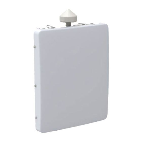
- Page 5 B Checklist ..................... 45 C Abbreviations ..................46 Figures Figure 1: AirSpeed 1030 B48 (GPS Attached) ..................13 Figure 2: AirSpeed 1030 B48 Front View ..................... 17 Figure 3: Workflow ..........................18 Figure 4: AirSpeed 1030 B48 Top Ports ....................21 Figure 5: AirSpeed 1030 B48 Bottom Ports ..................
- Page 6 Figure 53: Connecting Antenna RF Cable .................... 43 Tables Table 1: AirSpeed 1030 B48 ETSI Maximum Output TX Power ............11 Table 2: AirSpeed 1030 B48 FCC Maximum Output TX Power ............11 Table 3: Supported Frequency Bands ....................11 Table 4: Power Consumption ........................
-
Page 7: Document Information
AirSpeed 1030 B48 Installation Guide Document Information Abstract This document details procedures for installing the Airspan’s AirSpeed 1030 B48 Pico-class LTE eNodeB variant. Revision History Revision Details Date Summary of Changes Rev 0.1 – 0.5 Initial document – draft June 2020 ... -
Page 8: Warnings And Cautions
Warnings and Cautions Human Exposure to Radio Frequencies The AirSpeed 1030 B48 should be installed and operated from a minimum safe distance of at least 24.8 in. (63 cm) and installed higher than 2 meters to prevent unauthorized access. Avertissement et Precautions d’Utilisation Exposition des personnes aux fréquences radioélectriques... -
Page 9: Important Safety Instructions
Toute enfreinte a ces obligations peut annuler la garantie délivrée par Airspan pour ces produits et peut exposer l’utilisateur final ou le fournisseur de services a des dommages légaux et financiers. -
Page 10: Warning Of Hazardous Voltages
Substances Hazardous to Health Regulations 1989 and the Dangerous Substances Regulations 1990). At the end of any Airspan products life cycle, the customer should consult with Airspan to ensure that the product is disposed of in conformance with the relevant regulatory requirements. -
Page 11: Ul Information
This equipment is in compliance with the essential requirements and other relevant provisions of Directive 2014/53/EU. Español: Por medio de este Airspan, declara que la unidad cumple con los requisitos esenciales y cualquier otra disposición aplicable o exigible de la Directiva 2014/53 / UE. Greek: ΜΕ... - Page 12 2014/53 / EU. Íslenska: Airspan lýsir hér með yfir að þessi eining uppfylli grunnkröfur og aðrar kröfur tilskipunar 2014/53 / ESB. Norsk: Airspan erklærer herved at utstyrsenheten oppfyller grunnleggende krav og andre relevante krav i direktiv 2014/53 / EU.
-
Page 13: Maximum Output Tx Power
1030 21.92 @ 20MHz 46.92 @20MHz Note: The AirSpeed 1030 requires operation using an Airspan FCC-specific version of Netspan acting as a CBRS Domain Proxy. Caution: Do not set maximum output TX total power to higher than local regulations. Product Variants... -
Page 14: Power Consumption
AirSpeed 1030 B48 Installation Guide Power Consumption Table 4: Power Consumption Nominal Power Consumption Max Nominal Power Power Source Consumption (W) Note: Nominal Power Consumption (W) - refers to average power consumption over time. DUG01623 Airspan Commercial and Internal Use... -
Page 15: External Antennas (Optional)
AirSpeed 1030 B48 Installation Guide External Antennas (Optional) AirSpeed 1030 B48 can be connected to external antennas (if required) via four (4) N-Type female connectors located at the top panel. The antenna should be mounted to its appropriate mounting facility. -
Page 16: About This Document
AirSpeed 1030 B48 Installation Guide About This Document Purpose This guide provides the workflow and step-by-step procedures for installing the Airspan’s AirSpeed 1030 B48, Pico-class LTE eNodeB variant. These procedures include: Verify prerequisites Install Back bracket & Pole/Wall bracket ... -
Page 17: Related Reading
AirSpeed 1030 B48 Installation Guide Related Reading The following documents contain related information: AirSpeed 1030 B48 Product Datasheet Airspan LTE Commissioning Manual DUG01623 Airspan Commercial and Internal Use... -
Page 18: Customer Care Help Desk
Customer Care Help Desk Airspan’s Customer Care Help Desk offers prompt and efficient customer support services. To avail Airspan’s Customer Care Help Desk support, you must be a registered user and must Note: have a valid support contract. To register, click here and fill the Registration form. -
Page 19: Introduction
AirSpeed 1030 B48 provides high-speed data, mobility, Voice over LTE, and broadcast/multicast services. AirSpeed 1030 B48 is a super compact, easy to install eNodeB, allowing an operator to deploy LTE broadband services on any Street Furniture, rooftop or building front AirSpeed 1030 B48 is a dual sector / carrier 2x2 MIMO product with integrated front antenna. -
Page 20: Getting Started
The Workflow to install the AirSpeed 1030 B48 is displayed in the following diagram: Figure 3: Workflow 2.2 AirSpeed 1030 B48 Installation Checklist Plan the installation of the AirSpeed 1030 B48 by using the Installation Checklist, which you can find as a removable job aid in Appendix B for this guide. -
Page 21: Verifying Prerequisites
Set up requirements for the installation is detailed in the Job Sheet, see Appendix 3.1 Verifying Site Requirements To set up the AirSpeed 1030 B48, an IP connection to a Netspan server is required. 3.2 Verify Installation Requirements 3.2.1 Verify the Tools Table 6. -
Page 22: Verify The Parts And Kits
Accessories (ordered separately) GPS Antenna Kit GPS-ANT-4 GPS Antenna with Interference Rejection AirSpeed 1030 AS103-U-PMK-1 AirSpeed 1030 B48 mounting kit for universal pole 50 - 300 mm (2.0 to 11.8 inch) pole and wall including: Mounting KIT 1 - Pole mount Bracket... -
Page 23: Power Supply
AirSpeed 1030 B48 Installation Guide 3.2.3 Power Supply AirSpeed 1030 B48 supports direct connection to -48VDC power source: Operational Voltage Range: -40.5 to -57 VDC 3.2.4 Connections The following diagrams display the connections on the top and bottom panels of the AirSpeed 1030 B48. -
Page 24: Figure 5: Airspeed 1030 B48 Bottom Ports
AirSpeed 1030 B48 Installation Guide Figure 5: AirSpeed 1030 B48 Bottom Ports Note: When the Serial port or one of the backhaul ports are not in use it should be sealed with a cap or plug to keep it secured and environmentally protected. -
Page 25: Physical Dimensions
1 Kg. / 2.2 Lbs. (Bracket Base) 3.2.6 Environmental Note: AirSpeed 1030 B48 is not meant to be used in a Marine environment. AirSpeed 1030 B48 meets the following environmental requirements: IEC 60529 IEC 60068 ETSI EN 300-019-2-4 Operational (non-weather protected equipment) ... -
Page 26: Leds Display
AirSpeed 1030 B48 Installation Guide 3.3 LEDs Display Two (2) LEDs appear on the bottom of the unit, providing unit status indication. When powering up refer to the following table for indication of current status: Table 10: LED Display Name... -
Page 27: Airspeed 1030 B48 Installation
Pole Mounting Wall mounting The AirSpeed 1030 B48 Mounting Kit - includes a back bracket and pole/wall mounting bracket for fastening the unit to a pole or on a wall. Prior to installation the back bracket must be assembled on the AirSpeed unit and then the mounting bracket must be affixed in place on either the pole or a wall. -
Page 28: Connecting The Gps Antenna
The GPS Antenna Kit is ordered separately. Note: AirSpeed 1030 B48 works only with GPS antennas that are approved by Airspan. The following describes the connection of the GPS antenna which is installed directly to the top of the unit. -
Page 29: Pole Mounting Assembly
4.4 Pole Mounting Assembly Caution: Mount the AirSpeed 1030 B48 unit in an orientation such that it’s ports (located on the bottom) face downwards. This prevents rain water from settling on the port, and thereby, avoiding damage to the unit such as corrosion and electrical short–circuiting. -
Page 30: Figure 9: Mounted On Pole
AirSpeed 1030 B48 Installation Guide The following displays the AirSpeed 1030 B48 mounted on a pole. Figure 9: Mounted on Pole DUG01623 Airspan Commercial and Internal Use... -
Page 31: Wall Mount Assembly
4.5 Wall Mount Assembly The following describes the wall mounting procedure: 1. Select the location on the wall to mount the AirSpeed 1030 B48 mounting bracket. 2. Position the mounting (base) bracket onto the wall at the required height and mark where to drill the holes. -
Page 32: Tilt Adjustment
AirSpeed 1030 B48 Installation Guide 4.6 Tilt Adjustment On the AirSpeed 1030 B48 it is possible, after assembly to adjust the unit’s tilt, either up or down. This allows for maximum system optimization and reduce interference while increasing coverage. There are adjustment slots located on the sides of unit body where it is attached to the Mounting bracket. -
Page 33: Connect And Manage Cables
(SFP) cable to the AirSpeed 1050 unit. Note: Grounding cable, Fiber cables, SFP connector adaptor and AC power cable. Ethernet cables and RJ45 copper connector adaptor are not supplied as part of the AirSpeed 1030 B48 and can be ordered separately. 5.1 Grounding... -
Page 34: Figure 14: Open Housing Lock
AirSpeed 1030 B48 Installation Guide Open the housing lock by sliding up then lift the clamp handle, Figure 14: Open Housing Lock Separate the housing into its component sections. Insert the gland nut through the front end of LC Duplex assembly. -
Page 35: Figure 18: Pass Cable Thru Housing
AirSpeed 1030 B48 Installation Guide Figure 18: Pass Cable thru Housing Insert the LC Duplex cable into the transceiver. A “click” is heard when engaged. Figure 19: Insert Cable into Transceiver Insert the holder subset section from the front end of Transceiver. -
Page 36: Figure 22: Holder Into Transceiver
AirSpeed 1030 B48 Installation Guide Figure 22: Holder into Transceiver 12. Lift the lever of housing base slightly so that the rubber gland, tightening cone and gland nut can be inserted and tightened correctly. Figure 23: Lift Lever 13. Push to insert the rubber gland. -
Page 37: Copper Ethernet Cable Preparation
AirSpeed 1030 B48 Installation Guide Figure 26: Tighten Gland Nut 16. Insert the connector into the SFP port on the bottom of the chassis. Verify that the connector’s latch faces the rear of the unit to enable potential unlocking. 17. Close the lever and secure the lock by sliding the secondary lock/button, so that lever can’t be lifted. -
Page 38: Figure 29: Gland Nut On Cable
AirSpeed 1030 B48 Installation Guide Figure 29: Gland Nut on Cable Insert the “split tightening cone” from the side of the cable. Figure 30: Insert Tightening Cone on Cable Insert the “split rubber gland” from side of the cable. Note: Inner diameter of rubber gland is in the 5.8mm to 6.8mm or 8.8mm to 9.8mm range. -
Page 39: Figure 33: Insert Holder Onto Rj45
AirSpeed 1030 B48 Installation Guide Figure 33: Insert Holder onto RJ45 Fix the holder into the housing base. A “click” is heard when engaged. Figure 34: Holder into Housing Base Ensure correct alignment of the RJ45 in the hosing by raising the lever to allow free movement and then push the RJ45 plug into the plug cap to ensure proper location, then lock the cap. -
Page 40: Dc Cable Preparation
Figure 39: Secure Housing Lock 5.4 DC Cable Preparation The following demonstrates the recommended assembly instructions, hardware and tool requirements for the proper DC cable assembly used by Airspan products. Note: Power Cable: Diameter - 8.4mm to 9.4mm ... -
Page 41: Figure 40: Stripping Dimensions (Dc Cable)
AirSpeed 1030 B48 Installation Guide Warning: This unit incorporates double pole/neutral fusing. Both the Line & Neutral have fuses in them. Warning: The onsite source circuit breaker (6A) should be gang operated, two (2) pole (single phase type). The following displays the proper steps for DC cable preparation: Strip back and remove the outer sheath to a length of 9.0mm±... -
Page 42: Figure 43: Insert Gland Nut
AirSpeed 1030 B48 Installation Guide Figure 43: Insert Gland Nut Loosen the strap clamp and feed the prepared end of the source power cable into the inner part of the DC connector housing. Figure 44: Pass DC Cable Thru Secure the prepared ends of the cable into the inner part of the connector housing and tighten the 2 screws. -
Page 43: Figure 47: Align Marks + Click In Place
AirSpeed 1030 B48 Installation Guide Figure 47: Align Marks + Click in Place Place the split rubber gland onto the cable. Figure 48: Place Split Rubber Gland 10. Place the tightening cone onto the split rubber gland. Figure 49: Place Tightening Cone on Split Gland 11. -
Page 44: Remote (External) Antenna Assembly
The AirSpeed 1030 B48 unit can utilize remotely attached antennas. For installation of the remotely mounted antennas follow the antenna manufacturer’s instructions and connect the antenna to the AirSpeed 1030 B48 using the appropriate cables. (Weather-proofed N- type Heliax RF cables (ordered separately). -
Page 45: Figure 53: Connecting Antenna Rf Cable
AirSpeed 1030 B48 Installation Guide Figure 53: Connecting Antenna RF Cable Caution: Do not over-tighten the RF connector. RF failures can result when the RF connector is over-tightened. DUG01623 Airspan Commercial and Internal Use... -
Page 46: A Job Sheet
AirSpeed 1030 B48 Installation Guide A Job Sheet This job sheet enables the users to keep track of their installation. It covers all the prerequisites required for accomplishing the AirSpeed 1030 B48 installation. Site Requirements Position on Pole / Wall... -
Page 47: B Checklist
B Checklist During installation, review and perform all the steps on this checklist (in the given order). This checklist is meant for the person who performs the AirSpeed 1030 B48 installation. Tip: To make sure you complete all the tasks, detach or print this checklist and use it as a job aid. -
Page 48: C Abbreviations
AirSpeed 1030 B48 Installation Guide C Abbreviations Table 11: ABBREVIATIONS & DEFINITIONS Term Expansion 3GPP 3rd Generation Partnership Project, responsible for LTE AWGN Additive White Gaussian Noise is a channel model in which the only impairment to communication is a linear addition of white noise with a constant spectral density and a Gaussian distribution of amplitude. - Page 49 AirSpeed 1030 B48 Installation Guide Term Expansion Mobility Management Entity is the key control-node for the LTE access-network. It is responsible, among other things for idle mode UE tracking and paging procedure including retransmissions MTBF Mean Time Between Failures Network Listening...
Need help?
Do you have a question about the AirSpeed 1030 B48 and is the answer not in the manual?
Questions and answers