Sign In
Upload
Manuals
Brands
Airspan Manuals
Network Hardware
AirSpeed 1050 B3
Airspan AirSpeed 1050 B3 Manuals
Manuals and User Guides for Airspan AirSpeed 1050 B3. We have
1
Airspan AirSpeed 1050 B3 manual available for free PDF download: Installation Manual
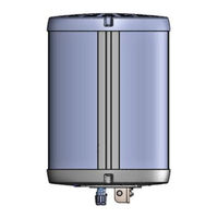
Airspan AirSpeed 1050 B3 Installation Manual (48 pages)
Brand:
Airspan
| Category:
Network Hardware
| Size: 1 MB
Table of Contents
Table of Contents
3
Document Information
8
Document Approvals
8
Revision History
8
Warnings and Cautions
9
Human Exposure to Radio Frequencies
9
Avertissement Et Precautions D'utilisation
9
Radio Interference
9
Modifications
9
General
9
Général
10
Important Safety Instructions
10
Safety
10
Securite
11
Warning of Hazardous Voltages
11
Attention Aux Voltages Hasardeux
12
Adherence to European Directive 2014/53/EU
12
Warning Symbols
12
Service Information
12
UL Information
13
Lightning Protection
13
Outdoor Cabling
14
Declaration of Conformity
14
GPS Compliance
16
Maximum Output TX Total Power
17
Power Consumption
17
Product Variants
17
Table 1: Airspeed 1050 B3 FCC Maximum Output Total Power
17
Table 2: Power Consumption
17
Table 3: Variants
17
Antenna System
18
Figure 1: Airspeed 1050 B3
18
About this Document
19
Purpose
19
Intended Audience
19
Related Reading
19
Customer Care Help Desk
20
Airspan Encourages Comments
20
1 Introduction
21
Airspeed 1050 B3
21
Deployment
21
Figure 2: Airspeed 1050 B3
22
2 Verifying Prerequisites
23
Verify the Tools
23
Verify the Parts and Kits
23
Table 4. Tool Requirements - Mounting
23
Table 5: Airspeed 1050 B3 Components
23
3 Physical Description
25
Airspeed 1050 B3 Physical Dimensions
25
Figure 3: Airspeed 1050 B3 Overall Dimensions
25
Table 6. Airspeed 1050 B3 Physical Dimensions
25
Table 7. Airspeed 1050 B3 Material & Color
25
Bottom View
26
Power
26
Environmental
26
Figure 4: Airspeed 1050 B3 Bottom
26
Leds Display
27
Table 8. Airspeed 1050 B3 Environment Compliance
27
Table 9: LED Display
27
4 Installation of Airspeed 1050 B3
28
Figure 5: Positioning Overview
28
Mounting Adaptor Assembly
29
Mounting
29
Securing the Unit to the Pole Mounting Arm
29
Figure 6: Mounting Adaptor Assembly
29
Figure 7: Securing on Mounting Bracket
30
Figure 8: Airspeed 1050 B3 on Pole Mounting Arm (Example)
30
Connect and Manage Cables
31
Connecting the Ground Cable
31
TX Power Monitoring Port
31
Cable Connection
31
Figure 9: Ground Connection
31
Table 10: Outdoor Power Cable Requirements
31
AC Cable Preparation
32
Figure 10: Stripping Dimensions (AC Cable)
32
Figure 11: Open Housing Lock
32
Figure 12: Seperate into Sections
33
Figure 13: Insert Gland Nut
33
Figure 14: Pass Cable through
33
Figure 15: Insert Wire to Housing
34
Figure 16: AC Wire Placement
34
Figure 17: Tighten Three (3) Set Screws
34
Table 11: Wire Pinout
34
Figure 18: Cable Click in Place
35
Figure 19: Place Split Rubber Gland
35
Figure 20: Gland Size on Edge
35
Table 12: Recommended Gland Sizes
35
Figure 21: Place Tightening Cone on Split Gland
36
Figure 22: Tighten Gland Nut
36
Figure 23: Close the Lever
36
Figure 24: Secure Lock
36
Fiber Ethernet (SFP) Cable Preparation
37
Figure 25: AC Housing Lock Secured
37
Figure 26: Stripping Dimensions (SFP Cable)
37
Figure 27: Pre-Assembled LC Duplex Cable
37
Figure 28: Open Housing Lock
38
Figure 29: Gland Nut on Cable
38
Figure 30: Insert Tightening Cone on Cable
38
Figure 31: Insert Rubber Gland on Cable
38
Figure 32: Pass Cable Thru Housing
39
Figure 33: Insert Cable into Transceiver
39
Figure 34: Insert Holder over Thetransceiver
39
Figure 35: Holder into Housing Base
39
Figure 36: Holder into Transceiver
40
Figure 37: Lift Lever
40
Figure 38: Insert Gland
40
Figure 39: Insert Cone
40
Copper Ethernet Cable Preparation
41
Figure 40: Tighten Gland Nut
41
Figure 41: Secure Housing Lock
41
Figure 42: Pre-Assembled RJ45 Cable
41
Figure 43: Gland Nut on Cable
41
Figure 44: Insert Tightening Cone on Cable
42
Figure 45: Insert Rubber Gland on Cable
42
Figure 46: Insert Housing Onto Cable
42
Figure 47: Insert Holder Onto RJ45
42
Figure 48: Holder into Housing Base
43
Figure 49: Align RJ45 into Holder
43
Figure 50: Lift Lever
43
Figure 51: Insert Gland
43
Figure 52: Tighten Gland Nut
44
Figure 53: Secure Housing Lock
44
5 Removal of Airspeed 1050 B3
45
Tool Requirements
45
AC Cable Disconnection
45
Fiber Ethernet (SFP) Cable Disconnection
45
Copper Ethernet (RJ45) Cable Disconnection
45
Ground Cable Disconnection
45
Airspeed Removal from the Pole Mounting Arm
46
Figure 54: Removal from the Mounting Arm
46
A Job Sheet
47
B Abbreviations
48
Advertisement
Advertisement
Related Products
Airspan AirSpeed 1030 B48
Airspan AIRSTAR 1900
Airspan AIRSTAR 1200
Airspan AirSpeed 1000A
Airspan AIRVELOCITY 1901
Airspan AirSpeed-1200 eNB
Airspan AirSpeed 1050 Series
Airspan AirSpeed 1050 B40
Airspan AirStrand 1300
Airspan AirVelocity 1500
Airspan Categories
Network Hardware
Accessories
Wireless Access Point
Microphone system
Antenna
More Airspan Manuals
Login
Sign In
OR
Sign in with Facebook
Sign in with Google
Upload manual
Upload from disk
Upload from URL