Table of Contents
Advertisement
Quick Links
Advertisement
Table of Contents

Subscribe to Our Youtube Channel
Related Manuals for CORNING Everon 6000


Summary of Contents for CORNING Everon 6000
- Page 1 Everon™ 6000 v1.0 User Manual Corning Optical Communications www.corning.com...
- Page 2 User Manual Proprietary Information The information contained in this document is the sole property of Corning. The Disclosure of this information does not constitute the release of any proprietary rights therein. Permission to reproduce this information or parts disclosed herein must be obtained in writing from Corning.
- Page 3 Intended Users and Scope This manual is intended for Corning system installers, technicians and users. It is assumed that the user is familiar with the system and its units, and understands the basic functionality of the system. Contacting Technical Support HelpDesk Corning technical support contact information: email: cmatsg@corning.com...
- Page 4 For example, working with high voltage components Caution: Actions requiring special attention, to avoid possible damage to equipment Note: Hints and recommendations for working efficiently Corning Restricted and Confidential Proprietary - Controlled content UM - Everon 6000 DAS - 19-DEC-2020.docx| December 2020 |Page 4 of 170...
- Page 5 Notwithstanding the foregoing, Corning shall have no obligation under the Software Warranty if the Software is modified or used with hardware or software not supplied or approved by Corning or if the Software is subject to abuse, improper installation or application, accident, electrical or environmental over-stress, negligence in use, storage, transportation or handling.
- Page 6 Corning shall not be liable for any other damage including, but not limited to, indirect, special or consequential damages arising out of or in connection with furnishing of goods, parts and service hereunder, or the performance, use of, or inability to use the goods, parts and service.
- Page 7 EAWS-band 66 1710-1780 MHz 2110-2200 MHz WCS -band 30 2305-2315 MHz 2350-2360 MHz 2500 -band 41 2496-2690 MHz (TDD) Corning Restricted and Confidential Proprietary - Controlled content UM - Everon 6000 DAS - 19-DEC-2020.docx| December 2020 |Page 7 of 170...
- Page 8 Warning! Only use a special DC supply cable with connector Warning! Always keep DC IN connectors connected during the product operation Company Certification Corning products have met the approvals of the following certifying organizations: Certification Certification No.: 88061; Certification Issue Date: 26/06/2019 Initial Certification Date: 29/04/2007;...
- Page 9 User Manual v1.0 Corning Restricted and Confidential Proprietary - Controlled content UM - Everon 6000 DAS - 19-DEC-2020.docx| December 2020 |Page 9 of 170...
- Page 10 User Manual v1.0 Corning Restricted and Confidential Proprietary - Controlled content UM - Everon 6000 DAS - 19-DEC-2020.docx| December 2020 |Page 10 of 170...
- Page 11 Industrial Boosters may only be used by FCC licensees or those given express (individualized) consent of license. Corning Optical Communications Wireless certifies all of the VARs listed as licensed installers for Corning. For the list of licensed VARs, please contact the Technical Support Team at: onesupport@corning.com or + (1) 833 4CORNING (833-426-7646)
- Page 12 Revision Date Created by Reviewed by Changes NOV 2020 Yoni Henya Moti Shalev First issue Aloomit Godfarb Gila Shmueli Corning Restricted and Confidential Proprietary - Controlled content UM - Everon 6000 DAS - 19-DEC-2020.docx| December 2020 |Page 12 of 170...
-
Page 13: Table Of Contents
Connect Antenna ......................57 2.3.8 External RF Source (3.5 GHz) ..................57 2.3.9 Connect Power & POWER UP ..................58 Corning Restricted and Confidential Proprietary - Controlled content UM - Everon 6000 DAS - 19-DEC-2020.docx| December 2020 |Page 13 of 170... - Page 14 System Graphical User Interface (GUI) ................102 Main GUI Options ......................102 5.1.1 Devices Screen – Element Management ............... 102 5.1.2 Events Screen ......................120 Corning Restricted and Confidential Proprietary - Controlled content UM - Everon 6000 DAS - 19-DEC-2020.docx| December 2020 |Page 14 of 170...
- Page 15 Binding Table ................Error! Bookmark not defined. List of traps ........................148 APPENDIX A: Ordering Information and Specifications ........... 151 Ordering information | ....................165 Corning Restricted and Confidential Proprietary - Controlled content UM - Everon 6000 DAS - 19-DEC-2020.docx| December 2020 |Page 15 of 170...
-
Page 16: Introduction
Corning Everon 6000 high bandwidth distribution architecture provides preparedness for future radio technologies, broader spectrum, and new frequency bands. Due to its modular design and configuration flexibility, Corning Everon 6000 is highly scalable in terms of supported capacity (number of sectors, frequency bands, channels) and remote units (coverage), and can be easily configured to support a large variety of deployment scenarios including single and multi-building (“Campus”) network topologies. -
Page 17: Terminology, Acronyms, And Abbreviations
FRM — Fiber remote module* *FMM and FRM are part of the FCM (fiber connectivity module) solution Digital Router Unit Corning Restricted and Confidential Proprietary - Controlled content UM - Everon 6000 DAS - 19-DEC-2020.docx| December 2020 |Page 17 of 170... - Page 18 MRU — Mid-power remote unit HRU –High-power Remote Unit Network Operation Center Small Medium Venues CPRI Common Public Radio Interface Corning Restricted and Confidential Proprietary - Controlled content UM - Everon 6000 DAS - 19-DEC-2020.docx| December 2020 |Page 18 of 170...
- Page 19 Simple Network Management Protocol Transmission Control Protocol User Datagram Protocol User Equipment Uplink UTRAN Universal Terrestrial Radio Access Network Corning Restricted and Confidential Proprietary - Controlled content UM - Everon 6000 DAS - 19-DEC-2020.docx| December 2020 |Page 19 of 170...
-
Page 20: Applicable Documents
User Manual v1.0 Abbreviation Description Picture User Datagram Protocol 1.3 Applicable Documents Table 2: References Document Name Document # Corning Restricted and Confidential Proprietary - Controlled content UM - Everon 6000 DAS - 19-DEC-2020.docx| December 2020 |Page 20 of 170... -
Page 21: Everon™ 6000 1.0 Architecture Overview
User Manual v1.0 1.4 Everon™ 6000 1.0 Architecture Overview Corning Everon™ 6000 allows combining between Optical Network Evolution (ONE) platform, and the fully digital Corning Building Wireless System (BWS) platform, which incorporates the digital distribution units – Digital Router Unit (DRU) and remotes. -
Page 22: External Interfaces And Use Cases - Example
MIMO A/B MIMO A/B Remote location #1 Remote location #8 Up to 16 remotes (types: LRU, MRU, HRU) per DRU Corning Restricted and Confidential Proprietary - Controlled content UM - Everon 6000 DAS - 19-DEC-2020.docx| December 2020 |Page 22 of 170... - Page 23 NOTE: A single DRU can support both the low power and high power (LRU and HRU) units. However, if an application requires adding MRUs, a separate DRU will be required to support it. Corning Restricted and Confidential Proprietary - Controlled content UM - Everon 6000 DAS - 19-DEC-2020.docx| December 2020 |Page 23 of 170...
-
Page 24: Internal Sub-Units
CPRI format, and to route these signals to the remote units. The DRU supports all Corning digital remote antenna units’ flavours, for all services, power levels and antenna configurations (SISO or MIMO). Each DRU includes 4 F/O CPRI ports connected to the DCMs and 32 F/O CPRI ports for connection to the remote units. - Page 25 The MRU also provides CBRS/C-Band ready RF interface for future field upgrades. Remotes: Up to 16 SISO mid-power units per DRU Corning Restricted and Confidential Proprietary - Controlled content UM - Everon 6000 DAS - 19-DEC-2020.docx| December 2020 |Page 25 of 170...
- Page 26 HRU can also be installed outdoors Remotes: Up to 8 MIMO high- power units per DRU • Synchronization: 10 MHz clock domain Corning Restricted and Confidential Proprietary - Controlled content UM - Everon 6000 DAS - 19-DEC-2020.docx| December 2020 |Page 26 of 170...
-
Page 27: System Installation
Part Number HARDWARE – provided in the box DRU unit 703A045402 AC Power Cord 708A042301 DC Power Adapter 255760003 Corning Restricted and Confidential Proprietary - Controlled content UM - Everon 6000 DAS - 19-DEC-2020.docx| December 2020 |Page 27 of 170... - Page 28 10Mhz input clock 10Mhz output clock USB to mini-USB cable Note: for technical support usage only. Required TOOLS Screwdriver Corning Restricted and Confidential Proprietary - Controlled content UM - Everon 6000 DAS - 19-DEC-2020.docx| December 2020 |Page 28 of 170...
-
Page 29: Dru Interfaces
SFP ports Adjustable ➢ Back view bracket Ground Fan Vents ➢ Side view Bracket adjustable position holes Vents Corning Restricted and Confidential Proprietary - Controlled content UM - Everon 6000 DAS - 19-DEC-2020.docx| December 2020 |Page 29 of 170... -
Page 30: Mount The Dru In The 19'' Rack
1. Connect one side of the grounding cable to the DRU rear grounding point and secure with 4 mm screw and washer. 2. Connect the other side of the grounding cable to grounding. Grounding point Corning Restricted and Confidential Proprietary - Controlled content UM - Everon 6000 DAS - 19-DEC-2020.docx| December 2020 |Page 30 of 170... - Page 31 5. Plug the SFP cable into the remote port until it clicks. 6. connect the other edge of the cable to the remote unit Corning Restricted and Confidential Proprietary - Controlled content UM - Everon 6000 DAS - 19-DEC-2020.docx| December 2020 |Page 31 of 170...
-
Page 32: Verify Normal Operation
During power up all LEDS are lit behaviour After SW initialization only power, run and LAN are lit (The optical LEDS are off) Corning Restricted and Confidential Proprietary - Controlled content UM - Everon 6000 DAS - 19-DEC-2020.docx| December 2020 |Page 32 of 170... -
Page 33: Lru Installation
Wall Mounting Bracket (may also BR-LRU be used for pole) Side brackets for dual-unit configuration Combiner – for dual unit CR-LRU configuration Corning Restricted and Confidential Proprietary - Controlled content UM - Everon 6000 DAS - 19-DEC-2020.docx| December 2020 |Page 33 of 170... - Page 34 SFP+ Pluggable Transceivers (hot-pluggable optical transceiver module); Support for option 8 line-rate 10.1 Gbps, single mode SOFTWARE Required TOOLS Phillips Screwdriver Corning Restricted and Confidential Proprietary - Controlled content UM - Everon 6000 DAS - 19-DEC-2020.docx| December 2020 |Page 34 of 170...
-
Page 35: Lru Interfaces
User Manual v1.0 2.2.2 LRU Interfaces SFP+ Management port Power Antenna Ground Connector Amount Type Antenna Ground Management port Power SFP+ Corning Restricted and Confidential Proprietary - Controlled content UM - Everon 6000 DAS - 19-DEC-2020.docx| December 2020 |Page 35 of 170... -
Page 36: Combiner Interfaces
2. There may be some configurations/use-cases where a combiner is not required, as there is only one type of unit (either low or mid band) Corning Restricted and Confidential Proprietary - Controlled content UM - Everon 6000 DAS - 19-DEC-2020.docx| December 2020 |Page 36 of 170... - Page 37 User Manual v1.0 ➢ Combiner Connection Interfaces Diagram Corning Restricted and Confidential Proprietary - Controlled content UM - Everon 6000 DAS - 19-DEC-2020.docx| December 2020 |Page 37 of 170...
-
Page 38: Fully Connected System Diagram
1. Connect the bracket to the wall, using 4 screws, as shown in the figure below: WALL 4 screws 2. For a single unit: mount the LRU on the bracket, using 4 screws Corning Restricted and Confidential Proprietary - Controlled content UM - Everon 6000 DAS - 19-DEC-2020.docx| December 2020 |Page 38 of 170... - Page 39 User Manual v1.0 4 screws Corning Restricted and Confidential Proprietary - Controlled content UM - Everon 6000 DAS - 19-DEC-2020.docx| December 2020 |Page 39 of 170...
- Page 40 Connect between the two devices and the base bracket (already carrying the combiner), using 4 screws, as shown below: Mid-band Combiner in bracket Low band Combiner Corning Restricted and Confidential Proprietary - Controlled content UM - Everon 6000 DAS - 19-DEC-2020.docx| December 2020 |Page 40 of 170...
-
Page 41: Connect Cables
Then connect the cables as follows: • Ground, see 2.2.6.1 • Power, See 2.2.6.2 • SFP+, see 2.2.6.3 Corning Restricted and Confidential Proprietary - Controlled content UM - Everon 6000 DAS - 19-DEC-2020.docx| December 2020 |Page 41 of 170... - Page 42 4. Prepare the other end of the grounding wire and connect it to an appropriate grounding point at the site to ensure adequate earth ground Corning Restricted and Confidential Proprietary - Controlled content UM - Everon 6000 DAS - 19-DEC-2020.docx| December 2020 |Page 42 of 170...
- Page 43 Figure 3 Remove rubber stopper from port and from SFP+ Pluggable Transceiver and insert the SFP+ Pluggable Transceivers (hot-pluggable optical transceiver module) into the port. Corning Restricted and Confidential Proprietary - Controlled content UM - Everon 6000 DAS - 19-DEC-2020.docx| December 2020 |Page 43 of 170...
-
Page 44: Antenna
2. There may be some configurations/use-cases where a combiner is not required, as there is only one type of unit (either low or mid band) Corning Restricted and Confidential Proprietary - Controlled content UM - Everon 6000 DAS - 19-DEC-2020.docx| December 2020 |Page 44 of 170... -
Page 45: Combiner Cables
2. There may be some configurations/use-cases where a combiner is not required, as there is only one type of unit (either low or mid band) Corning Restricted and Confidential Proprietary - Controlled content UM - Everon 6000 DAS - 19-DEC-2020.docx| December 2020 |Page 45 of 170... -
Page 46: Verify Normal Operation
User Manual v1.0 2.2.9 Verify normal operation The following table describes the LRU LED behaviour. Corning Restricted and Confidential Proprietary - Controlled content UM - Everon 6000 DAS - 19-DEC-2020.docx| December 2020 |Page 46 of 170... -
Page 47: Mru (Digital Medium-Power Remote Unit) Installation
600/700, 800/850 and dMRU-AC supported dMRU-6781923- assembly with four dPAM modules - 600/700, 800/850, PCS and WCS DC Chassis Corning Restricted and Confidential Proprietary - Controlled content UM - Everon 6000 DAS - 19-DEC-2020.docx| December 2020 |Page 47 of 170... - Page 48 - 600/700, 800/850, PCS and WCS dMRU CHASSIS dMRU-CHS-ASM ASSEMBLY WITH: DOPTM, FAM, MID- PLANE, CAVITY FILTER, MUX Corning Restricted and Confidential Proprietary - Controlled content UM - Everon 6000 DAS - 19-DEC-2020.docx| December 2020 |Page 48 of 170...
- Page 49 Up to 900 meters LC/UPC SM DX Grounding cable: HRU-dHPOM Service-specific power amplifier modules (PAMs), that are NOT provided Corning Restricted and Confidential Proprietary - Controlled content UM - Everon 6000 DAS - 19-DEC-2020.docx| December 2020 |Page 49 of 170...
-
Page 50: Mru Interfaces
Reference source not found.). Any attempt to pull out the module without first releasing may cause damage. Corning will not be liable for damage of products resulting from improper handling during installation or repair. PAMs are entered to their relevant slots by matching the color of the PAM and the color on top of the slot. - Page 51 * MRU chassis requires 6U rack height availability * Rack nuts and screws not provided * Digital optical module & FAN are pre-installed in the chassis Corning Restricted and Confidential Proprietary - Controlled content UM - Everon 6000 DAS - 19-DEC-2020.docx| December 2020 |Page 51 of 170...
-
Page 52: Mount Chassis In 19-In Rack
Secure the unit in the rack via remaining applicable bracket holes using the appropriate rack nuts and screws Figure 4. Example of MRU Chassis Rack Installation Corning Restricted and Confidential Proprietary - Controlled content UM - Everon 6000 DAS - 19-DEC-2020.docx| December 2020 |Page 52 of 170... -
Page 53: Wall Mount
Reference source not found.). Any attempt to pull out the module without first releasing may cause damage. Corning will not be liable for damage of products resulting from improper handling during installation or repair. Caution: Due to the chassis + 6 DPAMS weight, it is recommended the unit is carried by two persons, to avoid damage to the system. - Page 54 User Manual v1.0 Figure 5: Wall Mount Bracket 2. Assemble the wall-mount bracket to MRU underside Corning Restricted and Confidential Proprietary - Controlled content UM - Everon 6000 DAS - 19-DEC-2020.docx| December 2020 |Page 54 of 170...
-
Page 55: Ground Mru Chassis
3. Insert anchors in wall, hang unit and tighten to secure Figure 6. Example of MRU Chassis wall Installation Corning Restricted and Confidential Proprietary - Controlled content UM - Everon 6000 DAS - 19-DEC-2020.docx| December 2020 |Page 55 of 170... - Page 56 7. Prepare the other end of the grounding wire and connect it to an appropriate grounding point at the site to ensure adequate earth ground Figure 7MRU Grounding Lug Corning Restricted and Confidential Proprietary - Controlled content UM - Everon 6000 DAS - 19-DEC-2020.docx| December 2020 |Page 56 of 170...
-
Page 57: Connect Fiber Sfp
User Manual v1.0 2.3.6 Connect Fiber SFP+ Note: use SFP+ from the approved list provided by Corning. 1. Remove the rubber stopper from the source port. 2. Push the SFP+ connector into the port, until it clicks (note that there is only one correct direction for plugging-in). -
Page 58: Connect Antenna
Note: This external RF cavity port is market specific and may not be applicable to certain markets For future CBRS/C-Band services at 3.5 GHz. Corning Restricted and Confidential Proprietary - Controlled content UM - Everon 6000 DAS - 19-DEC-2020.docx| December 2020 |Page 58 of 170... - Page 59 • Power input: 100-240 VAC/50-60 Hz • Power consumption: 620 W (maximum) • Maximum AC current consumption: 7 A Corning Restricted and Confidential Proprietary - Controlled content UM - Everon 6000 DAS - 19-DEC-2020.docx| December 2020 |Page 59 of 170...
- Page 60 3. Route DC pair from CLASS1 connector to local power source; Power input: 48 VDC (40-60 VDC) 15 A max Corning Restricted and Confidential Proprietary - Controlled content UM - Everon 6000 DAS - 19-DEC-2020.docx| December 2020 |Page 60 of 170...
-
Page 61: Verify Normal Operation
2. Refer to status LEDs on the top-left of the chassis door and on each PAM to confirm normal system operation according to the following table: Table 5: MRU Chassis and DOPTM LEDs Table 6: PAM LEDs Corning Restricted and Confidential Proprietary - Controlled content UM - Everon 6000 DAS - 19-DEC-2020.docx| December 2020 |Page 61 of 170... -
Page 62: Hru Installation
User Manual v1.0 Table 7: SFP LEDs 2.4 HRU Installation Corning Restricted and Confidential Proprietary - Controlled content UM - Everon 6000 DAS - 19-DEC-2020.docx| December 2020 |Page 62 of 170... -
Page 63: Head End Unit (Heu) Installation
The following figure described the optimal rack installations for a maximum 4x4 HEU-IHU configuration in shared and dedicated equipment scenarios Corning Restricted and Confidential Proprietary - Controlled content UM - Everon 6000 DAS - 19-DEC-2020.docx| December 2020 |Page 63 of 170... - Page 64 DRAU MI MO A/B MI MO A/B MI MO A/B MI MO A/B Remote location #1 Remote location #8 Corning Restricted and Confidential Proprietary - Controlled content UM - Everon 6000 DAS - 19-DEC-2020.docx| December 2020 |Page 64 of 170...
- Page 65 3. Insert the modules into the chassis, see 2.5.3 4. Connect the cables, see 2.5.4 5. Power On, see 2.5.5 6. Verify normal operation, see 2.5.6 Corning Restricted and Confidential Proprietary - Controlled content UM - Everon 6000 DAS - 19-DEC-2020.docx| December 2020 |Page 65 of 170...
-
Page 66: Verify Box Contents
RIX modules. *Additional lengths can be ordered: • PCKC20: L=20 in • PCKC63: L=63 in • PCKC79: L=79 in Corning Restricted and Confidential Proprietary - Controlled content UM - Everon 6000 DAS - 19-DEC-2020.docx| December 2020 |Page 66 of 170... - Page 67 • ACM Kit (Auxiliary Control Module) – installed in Auxiliary HEU units; provides management connections for the Auxiliary HEU. Corning Restricted and Confidential Proprietary - Controlled content UM - Everon 6000 DAS - 19-DEC-2020.docx| December 2020 |Page 67 of 170...
-
Page 68: Mount The Chassis
• Secure the unit in the rack via all applicable bracket holes using the appropriate rack nuts and screws. Installing Chassis in Rack Corning Restricted and Confidential Proprietary - Controlled content UM - Everon 6000 DAS - 19-DEC-2020.docx| December 2020 |Page 68 of 170... -
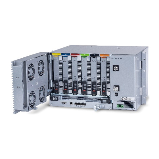
Page 69: Install The Modules In The Chassis
• Closing the ejectors (for relevant modules) • Tightening the captive screws Figure 11: Module Captive Screws and Ejectors Corning Restricted and Confidential Proprietary - Controlled content UM - Everon 6000 DAS - 19-DEC-2020.docx| December 2020 |Page 69 of 170... -
Page 70: Connect The Cables
For each RIM - connect the external RF source to the corresponding RIM (service specific) Simplex or Duplex QMA connectors: RIMs connections Corning Restricted and Confidential Proprietary - Controlled content UM - Everon 6000 DAS - 19-DEC-2020.docx| December 2020 |Page 70 of 170... - Page 71 The REF IN and REF OUT pilot clock ports must be connected in a closed loop as shown in Figure 10 • Both RIX modules of each chassis must be connected Corning Restricted and Confidential Proprietary - Controlled content UM - Everon 6000 DAS - 19-DEC-2020.docx| December 2020 |Page 71 of 170...
-
Page 72: Power On
For PSM-DC modules – refer to Quick Start Guide provided with module for wiring pinout. Verify that the Power Status LED on each PSM shows green. See Figure 13 for PS<-AC LED. Corning Restricted and Confidential Proprietary - Controlled content UM - Everon 6000 DAS - 19-DEC-2020.docx| December 2020 |Page 72 of 170... -
Page 73: Verify Nornal Operation
2.5.6 Verify NORNAL Operation If RF source is operational, verify that the RIM, DCM and HCM/ACM LEDs indicate normal operation Corning Restricted and Confidential Proprietary - Controlled content UM - Everon 6000 DAS - 19-DEC-2020.docx| December 2020 |Page 73 of 170... -
Page 74: Integrated Headend Unit (Ihu) Installation
IHU supports the following expansion connection options: To a single IHU NOTE: If DCM cards are available, ensure they are installed in the IHU only (not in the HEU)! Corning Restricted and Confidential Proprietary - Controlled content UM - Everon 6000 DAS - 19-DEC-2020.docx| December 2020 |Page 74 of 170... - Page 75 5. If needed: connect additional head end units, see 2.6.5 6. Power On, see 2.6.5 7. Verify normal operation, see 2.6.7 Corning Restricted and Confidential Proprietary - Controlled content UM - Everon 6000 DAS - 19-DEC-2020.docx| December 2020 |Page 75 of 170...
Need help?
Do you have a question about the Everon 6000 and is the answer not in the manual?
Questions and answers