
Subscribe to Our Youtube Channel
Related Manuals for SMC Networks VHL


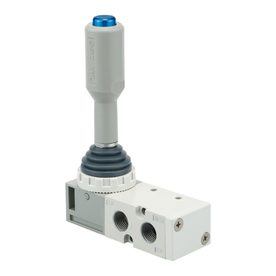
Summary of Contents for SMC Networks VHL
- Page 1 Doc no.DOC1080021 Product Name Hand Lever Valve Model / Series / Product Number...
-
Page 2: Table Of Contents
Contents 1. Safety Instructions 2~ 3 2. Specific Product Precautions 4~ 8 3. Installation 8~11 4. Application 5. Specifications 6. Troubleshooting 7. Construction 13~15 - 1 -... -
Page 3: Safety Instructions
Hand Lever Valve / VHL Series Safety Instructions These safety instructions are intended to prevent hazardous situations and/or equipment damage. These instructions indicate the level of potential hazard with the labels of “Caution,” “Warning” or “Danger.” They are all important notes for safety and must be followed in addition to International Standards (ISO/IEC) and other safety regulations. -
Page 4: Limited Warranty And Disclaimer/Compliance Requirements
Hand Lever Valve / VHL Series Safety Instructions Caution We develop, design, and manufacture our products to be used for automatic control equipment, and provide them for peaceful use in manufacturing industries. Use in non-manufacturing industries is not covered. Products we manufacture and sell cannot be used for the purpose of transactions or certification specified in the Measurement Act. -
Page 5: Specific Product Precautions
2. Specific Product Precautions Design/ Selection Design/ Selection Warning Warning (1) Confirm the specifications. (7) Release of residual pressure This product is designed to be used only in a For maintenance purposes install a system for compressed air system (including vacuum). releasing residual pressure. -
Page 6: Installation
Design/ Selection Mounting Warning Warning (14) If the product is not operated for a (1) Operation Manual prolonged period, it may take some time for Install the product and operate it only after the valve to recover due to sticking of the reading the Operation Manual carefully and seal. -
Page 7: Air Supply
Piping Air Supply Warning Caution (2) When there is a large amount of drainage (1) Refer to the Fittings and Tubing Compressed air containing a large amount of Precautions for handling one-touch drainage can cause the malfunction of fittings. pneumatic equipment. An air dryer or water separator should be installed upstream from (2) Preparation before piping filters. -
Page 8: Operating Environment
Operating environment Maintenance Warning Warning Perform maintenance inspection (1) Do not use in an atmosphere containing according to the procedures indicated in the corrosive gases, chemicals, sea water, operation manual. water, water steam, or where there is direct If handled improperly, malfunction or damage contact with any of these. -
Page 9: Installation Of Accessories
Therefore, the dimensions of the fittings to be used should first be confirmed in their respective catalogs. Fittings whose compliance with the VHL series is already confirmed are stated below. If the fitting within the applicable range is selected, there will not be any interference. - Page 10 A) 3-2 Dust boot installation (1) Install the dust boot before use. Install the dust boot so that it is hooked at the step of Dust boot the lever and the head cover, shown in blue. After installation, shift the lever to ensure that the dust boot is securely in the groove.
- Page 11 B) For Shift prevention lock B) 3-1 Remove the set nut Moving the dust boot (1) Remove the dust boot from the groove and move it to the position shown. If the dust boot remains installed in the groove, subsequent actions will be difficult. Removed from groove portion Allow the top and bottom edges of the dust boot to be removed from the groove respectively.
-
Page 12: Application
B) 3-3 Dust boot installation (1) Install the dust boot before use. Install the dust boot so that it is hooked at the step of the lever and the head cover shown in blue. After installation, shift the lever to ensure that the dust boot is securely in the groove. -
Page 13: Troubleshooting
6. TROUBLE SHOOTING Should any trouble be found during operation, trace the source of the trouble in the following order and take corrective action. Trouble phenomenon Cause expected Remedy ・ In case of ingress of foreign matter, Intrusion of foreign matter remove foreign matter by air blow of piping and then replace valve. -
Page 14: Construction
7. Construction VHL21*S-*02 (Spring return type) - 3-position closed center - 3-position exhaust center Spring return closed center Spring return exhaust center VHL212S-*02 (Spring return type) - 2-position Spring return Description Material Note Head Cover Gray Spool valve Aluminum alloy, HNBR,POM Lever Stainless steel Joint... - Page 15 VHL21*D-*02 (Detent type) - 3-position closed center - 3-position exhaust center Detent closed center Detent exhaust center VHL212D-*02 (Detent type) - 2-position Detent Description Material Note Head Cover Gray Spool valve Aluminum alloy, HNBR,POM Lever Stainless steel Joint Carbon steel Handle Gray Handle cap...
- Page 16 VHL21*W-*02 (Shift prevention lock type) - 3-position closed center - 3-position exhaust center Shift prevention lock closed center Shift prevention lock exhaust center VHL212W-*02 (Shift prevention lock type) - 2-position Shift prevention lock Description Material Note Head Cover Gray Spool valve Aluminum alloy, HNBR,POM Lever Stainless steel...
- Page 17 Revision history 4-14-1, Sotokanda, Chiyoda-ku, Tokyo 101-0021 JAPAN Tel: + 81 3 5207 8249 Fax: +81 3 5298 5362 https://www.smcworld.com Note: Specifications are subject to change without prior notice and any obligation on the part of the manufacturer. © SMC Corporation All Rights Reserved...
Need help?
Do you have a question about the VHL and is the answer not in the manual?
Questions and answers