Table of Contents
Advertisement
Advertisement
Table of Contents

Related Manuals for Dahua DHI-ASI7213X-V1-T1


Summary of Contents for Dahua DHI-ASI7213X-V1-T1
- Page 1 Face Recognition Access Controller User’s Manual User’s Manual V1.0.0...
- Page 2 Foreword General This manual introduces the installation and basic operations of the Face Recognition Access Controller (hereinafter referred to as "access controller"). Safety Instructions The following categorized signal words with defined meaning might appear in the manual. Signal Words Meaning Indicates a high potential hazard which, if not avoided, will result DANGER in death or serious injury.
- Page 3 errors in print. If there is any doubt or dispute, we reserve the right of final explanation. Upgrade the reader software or try other mainstream reader software if the manual (in PDF format) cannot be opened. All trademarks, registered trademarks and the company names in the manual are the ...
-
Page 4: Important Safeguards And Warnings
Important Safeguards and Warnings This chapter describes the contents covering proper handling of the access controller, hazard prevention, and prevention of property damage. Read these contents carefully before using the access controller, comply with them when using, and keep them well for future reference. Operation Requirement Do not expose the access controller to direct sunlight or heat source. -
Page 5: Table Of Contents
Table of Contents Foreword ..............................I Important Safeguards and Warnings ....................III 1 Overview ..............................1 Introduction ........................... 1 Features ............................1 Application ............................. 1 Dimension and Component ......................2 2 Connection and Installation ......................... 4 Cable Connections ........................4 Installation Notes........................... - Page 6 3.10.9 Reboot ..........................29 USB ............................30 3.11.1 USB Export ........................30 3.11.2 USB Import ........................31 3.11.3 USB Update ........................31 Features ............................ 31 3.12.1 Privacy Setting ........................ 33 3.12.2 Result Feedback ......................34 Record ............................36 Auto Test............................ 37 System Info ..........................
- Page 7 4.11.3 Onvif User ........................69 Maintenance ..........................69 Configuration Management ...................... 70 Upgrade ............................ 70 Version Information ........................71 Online User ..........................71 System Log ..........................71 4.17.1 Querying Logs ........................ 72 4.17.2 Backup Logs ........................72 4.17.3 Admin Log ........................72 Exit ............................
-
Page 8: Overview
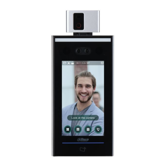
Overview Introduction The access controller is an access control panel that supports unlock through faces, passwords, cards, and their combinations. Features LCD display, the resolution of 7-inch access controller is 1024 × 600. Support face unlock, IC card unlock, and password unlock; unlock by period. ... -
Page 9: Dimension And Component
Networking Dimension and Component Dimensions and components of model X (mm [inch]) Table 1-1 Component description (1) Name Name Temperature monitoring unit Dual cameras Display... - Page 10 Dimensions and components of model Y (mm [inch]) Table 1-2 Component description (2) Name Name Temperature monitoring unit Display IR light Card swiping area Phototransistor White LED illuminator Dual cameras...
-
Page 11: Connection And Installation
Connection and Installation Cable Connections The cable connection of model X and model Y is the same. Here takes model X as an example. The access controller needs to be connected to devices like sirens, readers, and door contacts. Cable connections Table 2-1 Component description Name USB port... - Page 12 Port Cable Color Cable Name Description Blue CASE Tamper alarm input of the external card reader. Wiegand D1 input (connected to external card White reader)/output (connected to controller). Wiegand D0 input (connected to external card Green reader)/output (connected to controller). Connected to external reader and verify card Brown number.
-
Page 13: Installation Notes
Port Cable Color Cable Name Description purple Black RS-232 receiving port. Black RS-232 sending port. orange Black Connected to the common GND port. blue Black Used for door contact detection. gray CON3 Black PUSH1 Door open button of door No.1 green Black DOOR1_CO... - Page 14 If there is no suitable indoor environment (including areas directly facing indoor and outdoor areas, and outdoor doorways), set up a temporary passage with stable ambient temperature for temperature monitoring. The factors such as sunlight, wind, cold air, and air conditioning cold and warm air can ...
-
Page 15: Installation
Installation The installation of model X and model Y is the same. This section takes model X as an example. Make sure that the distance between the camera and ground is 1.4 meters. Installation height Installation diagram... - Page 16 Installation Procedure Fix the temperature monitoring unit to the bracket with 3 screws. Drill six holes (five bracket installation holes and one cable entry) in the wall according to holes in the bracket. Fix the bracket on the wall by installing the expansion screws into the six bracket installation holes.
-
Page 17: System Operations
System Operations Basic Configuration Procedure Basic configuration procedure Common Icons Table 3-1 Icon description Icon Description Main menu icon. Confirm icon. Turn to the first page of the list. Turn to the last page of the list. Turn to the previous page of the list. Turn to the next page of the list. -
Page 18: Standby Interface
Initialization Administrator and password set on this interface are used to log in to the web management platform. The administrator password can be reset through the email address you entered if the administrator forgets the password. The password must consist of 8 to 32 non-blank characters and contain at least two types ... -
Page 19: Main Menu
Homepage Table 3-2 Homepage description Description Unlock methods: Card, face, fingerprint, and password. When card, face, fingerprint, and password are all set as unlock mode, the password icon will not be displayed at the upper-left corner of the access controller. Date &... - Page 20 Different modes support different unlock methods, and the actual interface shall prevail. Administrator login...
-
Page 21: Unlocking Methods
Main menu Unlocking Methods You can unlock the door through faces, passwords, and cards. 3.6.1 Cards Put the card at the card swiping area to unlock the door. 3.6.2 Face Make sure that your face is centered on the face recognition frame, and then you can unlock the door. -
Page 22: Administrator Password
on the homepage. Enter the user ID, and then tap Enter the user password, and then tap The door is unlocked. 3.6.4 Administrator Password Enter the administrator password, and then you can unlock the door. There is only one administrator password for one access controller. The administrator password can unlock the door without being subject to user levels, unlock modes, periods, holiday plans, and anti-passback. - Page 23 New User Info Configure parameters on the interface. Table 3-3 New user parameter description Parameter Description Enter user IDs. The IDs can be numbers, letters, and their combinations, and User ID the maximum length of the ID is 32 characters. Each ID is unique. Enter names with at most 32 characters (including numbers, symbols, and Name letters).
-
Page 24: Viewing User Information
Parameter Description Admin: Administrators can unlock the door and also have parameter configuration permission. No matter whether there is an administrator in the access controller, administrator identity authentication is needed. Period You can set a period in which the user can unlock the door. Holiday You can set a holiday plan in which the user can unlock the door. - Page 25 3.8.1.1 Period Config You can configure 128 periods (weeks) whose number range is 0–127. You can set four periods on each day of a period (week). Users can only unlock the door in the periods that you set. 3.8.1.2 Holiday Group You can set group holidays, and then you can set plans for holiday groups.
-
Page 26: Unlock
3.8.2 Unlock There are three unlock modes: unlock mode, unlock by period, and group combination. Unlock modes vary with controller access models, and the actual controller access shall prevail. 3.8.2.1 Unlock Mode When the Unlock Mode is on, users can unlock through cards, faces, passwords, or any one of all the unlocking methods. - Page 27 Enable the Unlock Mode. means enabled. means not enabled. 3.8.2.2 Unlock by Period Doors can be unlocked through different unlock modes in different periods. For example, in period 1, the door can only be unlocked through cards; and in period 2, doors can only be locked through faces.
- Page 28 3.8.2.3 Group Combination Doors can only be unlocked by a group or groups that consist of more than two users if the Group Combination is enabled. Select Access > Unlock Mode > Group Combination. Group combination to create a group. Add a group Table 3-4 Group parameter Parameter...
-
Page 29: Alarm Configuration
Enable the Group Combination. means enabled. means not enabled. 3.8.3 Alarm Configuration Administrators can manage visitors’ unlock permission through alarm configuration. Select Access > Alarm. Alarm means enabled. means not enabled. Table 3-5 Parameters on the alarm interface Parameter Description After the anti-passback is enabled, users need to verify identities both for... -
Page 30: Door Status
Parameter Description Timeout door exceeds the Door Sensor Timeout time. The Door Sensor Timeout time range is 1–9999 seconds. Door Sensor Only when the Door Sensor On is enabled can the intrusion alarm and door sensor timeout alarm be triggered. 3.8.4 Door Status There are three options: NO, NC, and Normal. - Page 31 IP address configuration Table 3-6 IP configuration parameters Parameter Description NIC 1/2 Tap to configure parameters for the Ethernet port. IP Address/Subnet The IP address, subnet mask, and gateway IP address must be on the Mask/Gateway IP same network segment. Address DHCP (Dynamic Host Configuration Protocol).
-
Page 32: Serial Port Settings
Name Parameter Server IP Address IP address of the managing platform. Port Port number of the managing platform. Device ID Subordinate device number on the managing platform. 3.9.1.3 Wi-Fi You can connect the access controller to the network through Wi-Fi if the access controller has Wi-Fi function. -
Page 33: System
Wiegand Select Wiegand Input when an external card swipe mechanism is connected to the access controller. Select Wiegand Output when the access controller works as a reader that can be connected to the controller. Table 3-8 Wiegand output Parameter Description The Wiegand Output Type determines the card number or the digit... -
Page 34: Face Parameter
3.10.2 Face Parameter Face parameter Tap a parameter and do configuration, and then tap Table 3-9 Face parameter Name Description Face Recognition Face recognition accuracy can be adjusted. The larger the value is, Threshold the higher the accuracy will be. Max. -
Page 35: Image Mode
Name Description This function prevents people from unlocking by human face images Anti-fake Threshold or face models. Set whether to enable the body temperature monitoring. Temp Unit: Select a temperature unit. Temp Rect: Set whether to display the temperature monitoring box or not. -
Page 36: Fill Light Mode Setting
3.10.4 Fill Light Mode Setting You can select fill light modes according to your needs. There are three modes: Auto: When the photo sensor detects that the ambient environment is not dark, the fill light is normally off; otherwise, the fill light will be on. NO: The fill light is normally on. -
Page 37: Usb
Make sure that the USB is inserted before exporting user information and updating. During exporting or updating, do not pull out the USB or do other operations; otherwise the exporting or updating will fail. You need to import information from one access controller to the USB before using USB to ... -
Page 38: Usb Import
3.11.2 USB Import Only data in the USB that was exported from one access controller can be imported into another access controller. Select USB > USB Import. USB Import Select the data type that you want to import. Tap OK. Data in the USB flash drive will be imported into the access controller. - Page 39 Features Table 3-10 Feature description Parameter Description Privacy Setting See "3.12.1 Privacy Setting" for details. If the third-party card reader needs to be connected to the access through the wiegand output port, you need to enable the controller Card No. Reverse Card No.
-
Page 40: Privacy Setting
3.12.1 Privacy Setting Privacy setting Table 3-11 Features Parameter Description PWD Reset If the PWD Reset Enable function is enabled, you can reset the password. Enable The PWD Reset function is enabled by default. Hypertext Transfer Protocol Secure (HTTPS) is a protocol for secure communication over a computer network. -
Page 41: Result Feedback
Parameter Description Capture If you select ON, when a user unlocks the door, the user’s photo will be Photo automatically taken. This function is ON by default. Clear All Captured Tap the icon, and you can delete all captured photos. Photos Face Privacy Set different levels to blur the standby interface. - Page 42 User Photo & Name User photo & name Only Name Only name...
-
Page 43: Record
Success or Failure Success or failure Record You can search for all unlocking records. Select Record > Search Punch Records. -
Page 44: Auto Test
Search punch records Auto Test When you use the access controller for the first time or when the access controller malfunctioned, you can use auto test function to check whether the access controller can work normally. Do actions according to the prompts. -
Page 45: System Info
Auto test When you select Auto Test, the access controller will guide you to do all the auto tests. System Info You can view data capacity, device version, and hardware version of the access controller on the System Info interface. -
Page 46: Web Operations
Web Operations The access controller can be configured and operated on the web. Through the web you can set network parameters, video parameters, and access controller parameters; and you can also maintain and update the system. Initialization You need to set a password and an email address before logging in to the web for the first time. Open IE web browser, and enter the IP address (the default address is 192.168.1.108) of the access controller in the address bar, and then press Enter. - Page 47 When you need to reset the administrator password by scanning the QR code, you need an email address to receive the security code. Click Next. Auto check You can decide whether to select Auto Check or not. It is recommended that Auto Check be selected to get the latest program in time. Click Next.
-
Page 48: Login
Login Open IE web browser, enter the IP address of the access controller in the address bar, and press Enter. IE 8 and later are supported. Otherwise you might not log in to the web. Make sure that the computer used to log in to the web is in the same LAN with the ... - Page 49 Tips Read the tips. Click OK. Reset Password Scan the QR code on the interface, and you will get the security code. At most two security codes will be generated by scanning the same QR code. If security codes become invalid, to get more security codes, refresh the QR code. You need to send the content that you get after you scan the QR code to the ...
-
Page 50: Alarm Linkage
If wrong security codes are entered for consecutive five times, the administrator will be frozen for five minutes. Enter the security code you have received. Click Next. Reset and confirm the new password. The password should consist of 8 to 32 non-blank characters and contain at least two types of characters among upper case, lower case, number, and special character (excluding ' "... - Page 51 Modifying alarm linkage parameter Table 4-1 Alarm linkage parameter description Parameter Description Alarm Input You cannot modify the value. Keep it default. Name Enter a zone name. There are two options: NO and NC. Alarm Input Type If alarm input type of the alarm device that you purchased is NO, select NO;...
-
Page 52: Alarm Log
4.4.2 Alarm Log You can view the alarm type and time range in the Alarm Log interface. Select Alarm Linkage > Alarm Log. Alarm log Select a time range and alarm type, and then click Query. Query results Call Configuration The access controller can work as a door station and call other devices. - Page 53 Configure the parameters. Local (1) Table 4-2 Parameter description Parameter Description Device Type The access controller can only work as a unit door station. Enter a number to be identified by the management center. It should be Centre Call No. "888888"...
-
Page 54: Sip Server
Parameter Description the same. Mode1: Real-time call but the video and sound may be lagging with poor network. Transmission Mode Mode2: Not real-time call but ensures smooth video and sound. 4.5.2 SIP Server On the web, you can add door stations and indoor stations to the SIP server so that they can talk to each other. -
Page 55: Door Station Management
4.5.2.2 Other Device as SIP Server Log in to the web. Select Talkback Setting > SIP Server. Select Server Type as VTO and do not enable SIP Server. Configure the parameters SIP server (2) Table 4-4 SIP server parameter description (1) Parameter Description IP Address... - Page 56 Log in to the web. Select Talkback Setting > VTO No. Management. Click Add. VTO No. management Configure the parameters. Add a door station Table 4-5 Parameter description Parameter Description Rec No. Number of the door station. Register Password Keep the default value.
-
Page 57: Indoor Monitor Management
Parameter Description Build No. Cannot be configured. Unit No. Cannot be configured. IP Address IP address of the door station. Username Web login username and password for the door station. Password Click OK. 4.5.4 Indoor Monitor Management When the access controller works as the SIP server, add all relevant indoor monitors to call them. - Page 58 Add one indoor monitor Table 4-6 Parameter description Parameter Description First Name Last Name To differentiate each indoor monitor. Nick Name Room number of the indoor monitor. It can contain up to five digits and must be the same as the one ...
-
Page 59: Configuring The Managing Device
Click Add. Add indoor monitors in batches 4.5.5 Configuring the Managing Device When the access controller works as the SIP server, add other managing devices to call them. Log in to the web. Select Talkback Setting > VTS Management. Click Add. Add managing devices Enter the information. -
Page 60: Online Status
Added a managing device Modify a managing device. You need to update the information when the register password or IP address of the managing device change. Click and enter the new password or IP address, and then click OK. Delete a managing device. -
Page 61: Call Logs
Status 4.5.7 Call Logs You can check up to 1024 call logs. Log in to the web. Select Talkback Setting > Call. (Optional) Click Export Data to export all the logs. Call logs... -
Page 62: Data Capacity
Data Capacity You can see how many users, cards and face images that the access controller can hold on the Data Capacity interface. Data capacity Video Setting You can set parameters including data rate, image parameters (brightness, contrast, hue, saturation, and more), and exposure on the Video Setting interface. 4.7.1 Data Rate Data rate... -
Page 63: Image
Table 4-7 Data rate parameter description Parameter Description Video Standard There are two options: NTSC and PAL. Select a standard according to the video standard of your region. Channel There are two options: 1 and 2. 1 is white light camera and 2 is IR light camera. -
Page 64: Exposure
Select Wide Dynamic in the Backlight Mode. Table 4-8 Image parameter description Parameter Description Brightness The larger the value is, the brighter the images will be. Contrast is the difference in luminance or color that makes an object Contrast distinguishable. The larger the contrast value is, the greater the brightness and color contrast will be. -
Page 65: Motion Detection
Parameter Description 60Hz: When the utility frequency of alternating current is 60Hz, the exposure is automatically adjusted to make sure that there are no stripes on images. Outdoor: When Outdoor is selected, the exposure mode can be switched. You can select from: Auto: The access controller will automatically adjust brightness of images. - Page 66 Motion detection Press and hold the left mouse button, and then drag the mouse in the red area. The red rectangles are motion detection area. The default motion detection range is all the rectangles. To draw a motion detection area, you need to click Remove All first. ...
-
Page 67: Volume Setting
When grid number is smaller than the threshold, green line will appear; when grid number is more than the threshold, red line will appear. See. Click OK to finish the setting. 4.7.5 Volume Setting You can adjust volume of the access controller speaker. Volume setting 4.7.6 Image Mode There are three options: indoor, outdoor and other. -
Page 68: Face Detect
Local coding Click OK. Face Detect You can configure human face related parameters on this interface to increase the accuracy of the face recognition. Select Face Detect. - Page 69 Face detect Configure parameters. Table 4-10 Face detect parameter description Parameter Description Face Recognition The larger the value is, the higher the accuracy will be. Threshold Max. Angle of Face The larger the angle is, the wider range of the profiles will be Recognition recognized.
- Page 70 Parameter Description value is greater than 19. Infrared Light Adjust IR brightnees by dragging the scroll bar. When a person who does not have the access permission stands in Recognition front of the access controller and gets the face recognized, the Timeout controller will prompt that face recognition failed.
-
Page 71: Network Setting
Parameter Description between the monitored temperature and the actual temperature, you can correct the temperature deviation by this parameter. For example, if the monitored temperature is 0.5°C lower than the actual temperature, the correction value is set to 0.5°C; if the monitored temperature is 0.5°C higher than the actual temperature, the correction value is set to -0.5°C. -
Page 72: Port
Table 4-11 TCP/IP Parameter Description Ethernet Card Select to configure parameters of the card. IP Version There is one option: IPv4. MAC Address MAC address of the access controller. Static Set IP address, subnet mask, and gateway address manually. DHCP ... -
Page 73: Register
Click OK to complete the setting. 4.9.3 Register When connected to external network, the access controller will report its address to the server that is designated by the user so that clients can get access to the access controller. Select Network Setting > Auto Register. Select Enable, and enter host IP, port, and sub device ID. -
Page 74: Safety Management
Select Network Setting > P2P. Select Enable to enable P2P function. Click OK to complete the setting. Scan the QR code on your web interface to get the serial number of the access controller. Safety Management 4.10.1 IP Authority Select a cybersecurity mode as needed. IP authority 4.10.2 Systems 4.10.2.1 System Service... -
Page 75: User Management
System service 4.10.2.2 Creating Server Certificate Click Create Server Certificate, enter needed information, click Save, and then the access controller will reboot. 4.10.2.3 Downloading Root Certificate Click Download Root Certificate. Select a path to save the certificate on the Save File dialog box. Double-click on the Root Certificate that you have downloaded to install the certificate. -
Page 76: Onvif User
User management 4.11.3 Onvif User Open Network Video Interface Forum (ONVIF), a global and open industry forum with the goal of facilitating the development and use of a global open standard for the interface of physical IP-based security products. When ONVIF is used, administrator, operator, and user have different permission of ONVIF server. -
Page 77: Configuration Management
Maintenance Configuration Management You need to do configuration management, select unlock result feedback, Wiegand and serial settings for the access controller. When more than one access controller needs the same configuration, you can configure parameters for them by importing or exporting configuration files. Configuration management Upgrade You can select Auto Check to upgrade the system automatically. -
Page 78: Version Information
Version Information You can view information including MAC address, serial number, MCU version, web version, security baseline version, and system version. Online User You can view username, IP address, and user login time on the Online User interface. Online user System Log You can view and backup the system log on the System Log interface. -
Page 79: Querying Logs
System log 4.17.1 Querying Logs Select a time range and its type, click Query, and logs meet the conditions will be displayed. 4.17.2 Backup Logs Click Backup to back up the logs displayed. 4.17.3 Admin Log Enter Admin ID on the Admin Log interface, click Query, and then you will see the administrator’s operation records. -
Page 80: Exit
Admin log Hover the mouse cursor over , and then you can see detailed information of the current user. Exit Click , click OK, and then you will log out the web interface. -
Page 81: Faq
The access controller fails to start after power-on. Check whether the 12V power supply is correctly connected, and whether the power button is pressed. Faces cannot be recognized after the access controller powers on. Make sure that Face is selected in the unlock mode. See “3.8.2 Unlock”. Make sure that Face is selected as unlock mode in Access >... -
Page 82: Notes Of Temperature Monitoring
Notes of Temperature Monitoring Warm up the temperature monitoring unit for more than 20 minutes after power-on to enable the temperature monitoring unit to reach thermal equilibrium. Install the temperature monitoring unit in an indoor windless environment, and maintain the ... -
Page 83: Notes Of Face Recording/Comparison
Notes of Face Recording/Comparison Before Registration Glasses, hats, and beards might influence face recognition performance. Do not cover your eyebrows when wearing hats. Do not change your beard style greatly if you will use the device; otherwise face ... - Page 84 Do not shake your head or body, otherwise the registration might fail. Avoid two faces appear in the capture frame at the same time. Face Position If your face is not at the appropriate position, face recognition effect might be influenced. Appendix Figure 2-2 Appropriate face position Requirements of Faces Make sure that the face is clean and forehead is not covered by hair.
- Page 85 too far from the camera. Appendix Figure 2-3 Head position Appendix Figure 2-4 Face distance When importing face images through the management platform, make sure that image resolution is within the range 150 × 300–600 × 1200; image pixels are more than 500 × 500;...
-
Page 86: Cybersecurity Recommendations
Cybersecurity Recommendations Cybersecurity is more than just a buzzword: it’s something that pertains to every device that is connected to the internet. IP video surveillance is not immune to cyber risks, but taking basic steps toward protecting and strengthening networks and networked appliances will make them less susceptible to attacks. - Page 87 We suggest you to change default HTTP and other service ports into any set of numbers between 1024~65535, reducing the risk of outsiders being able to guess which ports you are using. Enable HTTPS We suggest you to enable HTTPS, so that you visit Web service through a secure communication channel.
- Page 88 Enable IP/MAC address filtering function to limit the range of hosts allowed to access the device.
Need help?
Do you have a question about the DHI-ASI7213X-V1-T1 and is the answer not in the manual?
Questions and answers