Table of Contents
Advertisement
Quick Links
Advertisement
Table of Contents

Related Manuals for Dahua DHI-ASA4214F


Summary of Contents for Dahua DHI-ASA4214F
- Page 1 Face Recognition Access and Time Attendance Terminal Quick Start Guide V1.0.1...
-
Page 2: Cybersecurity Recommendations
Cybersecurity Recommendations Mandatory actions to be taken towards cybersecurity 1. Change Passwords and Use Strong Passwords: The number one reason systems get “hacked” is due to having weak or default passwords. It is recommended to change default passwords immediately and choose a strong password whenever possible. - Page 3 ● Only forward the HTTP and TCP ports that you need to use. Do not forward a huge range of numbers to the device. Do not DMZ the device's IP address. ● You do not need to forward any ports for individual cameras if they are all connected to a recorder on site;...
- Page 4 Ideally, you want to prevent any unauthorized physical access to your system. The best way to achieve this is to install the recorder in a lockbox, locking server rack, or in a room that is behind a lock and key. 15.
-
Page 5: Foreword
Foreword General This document elaborates on structure, installation and system function of face recognition access and time attendance terminal. Safety Instructions The following categorized signal words with defined meaning might appear in the Manual. Signal Words Meaning Indicates a high potential hazard which, if not avoided, will result in death or serious injury. - Page 6 All the designs and software are subject to change without prior written notice. The product updates might cause some differences between the actual product and the Manual. Please contact the customer service for the latest program and supplementary documentation. There still might be deviation in technical data, functions and operations description, or ...
-
Page 7: Important Safeguards And Warnings
Important Safeguards and Warnings The following description is the correct application method of the device. Please read the manual carefully before use, in order to prevent danger and property loss. Strictly conform to the manual during application and keep it properly after reading. Operating Requirement Please don’t place and install the device in an area exposed to direct sunlight or near heat ... -
Page 8: Table Of Contents
Table of Contents Cybersecurity Recommendations ......................II Foreword ..............................V Important Safeguards and Warnings ....................VII 1 Product Overview ..........................1 1.1 Functional Features ........................1 1.2 External Dimension ........................2 2 Installation Guide ..........................3 2.1 Packing List ........................... 3 2.2 System Architecture ........................ -
Page 9: Product Overview
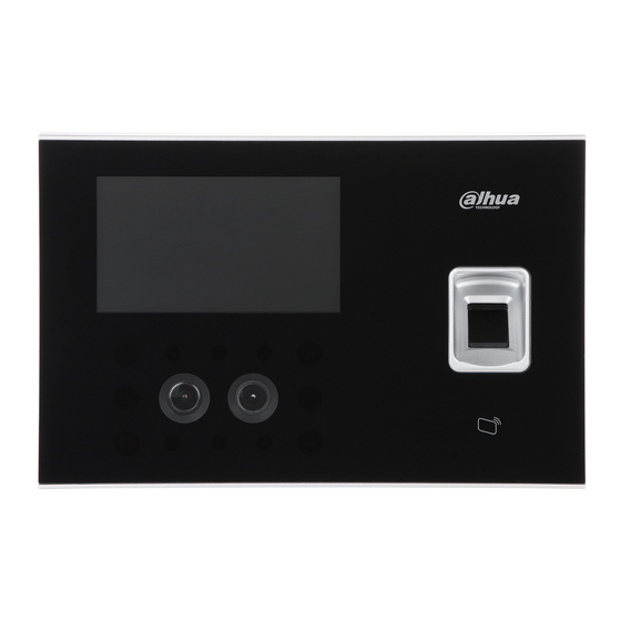
Product Overview Face recognition access and time attendance terminal is a generation of more powerful face recognition device that supports access control and attendance management. By integrating face, fingerprint, card and password identifications, this device is suitable for offices, factories, retail stores, schools and hospitals. -
Page 10: External Dimension
External Dimension External dimension of the device is shown in Figure 1-1. The unit is mm. Figure 1-1... -
Page 11: Installation Guide
Installation Guide Packing List Before installation, please check the package according to Table 2-1. Name Quantity Note Device Power adapter DC12V 2A Cable M4×30 cross recessed pan Fix the bracket to head flat-end screw concealed mount 1 bag Without concealed ... -
Page 12: Installation
Installation Installation of the device is shown in Figure 2-2 and Figure 2-4. Figure 2-2 Figure 2-3... -
Page 13: Panel And Port
Figure 2-4 Step 1 Drill holes according to the positions in Figure 2-3, and install expansion pipes into holes. Step 2 Install the bracket. If there is a concealed mount, fix the bracket onto concealed mount with screw A. Without the concealed mount or good fixation, fix the bracket onto the wall directly ... - Page 14 Figure 2-5 Figure 2-6 Figure 2-7...
-
Page 15: Wiring Description
Port Note CON1 Wiegand /RS485 input/output. CON2 Electric lock output, door sensor and exit button. CON3 Power port and network port. CON4 Alarm input/output port. Table 2-2 Wiring Description From left to right, terminal number is 1~8, as shown in Figure 2-7. 2.5.1 Wiring Description of Wiegand /RS485 Input/output This device works as a card reader, and can connect a card reader. - Page 16 Port Mark Note Lock control output CON2 (lock, Door sensor door contact and PUSH Exit button exit button) GND shared by door sensor and exit button Reserved Table 2-5 Figure 2-8 Figure 2-9 Figure 2-10...
-
Page 17: Wiring Description Of Power And Network Port
Figure 2-11 2.5.3 Wiring Description of Power and Network Port In CON3, corresponding terminals are described in Table 2-6. Port Mark Note Positive pole of power ERX- 100M network port CON3 (power and network Negative pole of power port) ERX+ ETX- 100M network port ETX+... - Page 18 Figure 2-12 Figure 2-13 External alarm input is shown in Figure 2-14. Figure 2-14...
-
Page 19: System Operation
System Operation Boot up Plug in power, and press switch button on the left to boot up the device. The device displays a white screen, and enters standby interface after 15s, as shown in Figure 3-2. Device Initialization Device initialization means to set admin, password and email during the first login. If the password is not set, the platform will fail to add the device. -
Page 20: Standby Interface
Standby Interface Unlock the door and check attendance with face, card and password. If you don’t operate in one interface for over 30s, it will return to standby interface. Figure 3-2 Customize the attendance event in “Features > Fn Key”. Please refer to the user’s manual for details. -
Page 21: User
Figure 3-3 User Add access and attendance users, customize department name and set super password. 3.5.1 New User Add a new user, including user ID, name, fingerprint, card number, password and face, so the user can unlock or check attendance with fingerprint, card or password. The system supports max. - Page 22 Parameter Note User ID Enter user ID, max. 8-digit number. Name Enter username, max. 32 characters. Collect fingerprints. One user can collect max. 3 fingerprints and every fingerprint shall be verified for 3 times. Please operate according to voice prompt. It will prompt “Registration Success” on completion. After success, pop up “Save it as Duress FP?”...
-
Page 23: User List
Parameter Note Photo Take a photo. When swiping a card, the screen displays the user’s photo. Department Users check attendance according to department shift. Shift Department shift: check attendance according to the shift of department where the user belongs to. ... - Page 24 : card verification. : password verification. User level displays the user’s level, including user and admin. Edit User Info Step 1 Select the line of the user to be edited. The screen displays “Edit User Info” interface, as shown in Figure 3-6. Figure 3-6 Step 2 Select a corresponding parameter to edit and modify it, and press...
-
Page 25: Unlock Mode
Unlock Mode Unlock mode includes any combination unlock, unlock config by period and group combination config. 3.6.1 Unlock Mode Unlock with any one or multiple combination of card, fingerprint, face and password. Select “Access > Unlock Mode > Unlock Mode”. Step 1 Step 2 Press up and down button to select the combination mode. -
Page 26: Group Combination
Press [Yes]. The system returns to “Unlock Mode” interface. Step 4 Press the switch after “Unlock by Period” to enable. Step 5 : enable. : disable. 3.6.3 Group Combination Set to unlock after authorized by multiple users or user groups. Select “Access >... -
Page 27: Lock Holding Time
Parameter Note Add users to the new group. Press [User]. Press in the pop-up interface. User Press to enter user ID. Repeat Step 2~ Step 3 and continue to add users. Max. 50 users can be added. Press , and press [Yes] to save according to interface prompt. Select unlock mode, including card, fingerprint, password and face. -
Page 28: Network Configuration
Figure 3-10 Enter “Lock Holding Time” and press Step 2 to save the setting. Network Configuration Select “Connection > Network Configuration”, and the screen displays Figure 3-11. Step 1 Figure 3-11 Step 2 Select adding mode according to actual situation. IP Address ... - Page 29 Parameter Note IP Address, Subnet Set device IP address, subnet mask and gateway, ensure that IP address Mask and Gateway and gateway are in the same network segment, and press to save. IP Address DHCP: Dynamic Host Configuration Protocol. Enable/Disable Enable DHCP function and obtain IP address automatically.
Need help?
Do you have a question about the DHI-ASA4214F and is the answer not in the manual?
Questions and answers