
Related Manuals for Dahua DHI-IPMECS-2201C


Summary of Contents for Dahua DHI-IPMECS-2201C
- Page 1 Access ANPR Kit User’s Manual V1.0.1 ZHEJIANG DAHUA VISION TECHNOLOGY CO., LTD. V1.0.0 ZHEJIANG DAHUA VISION TECHNOLOGY CO., LTD.
-
Page 2: Foreword
Foreword General This manual introduces the structure, installation and configurations of access ANPR kit (hereinafter referred to as "the Kit"). Models DHI-IPMECS-2201C DHI-IPMECS-2201C-IR Safety Instructions The following categorized signal words with defined meaning might appear in the Manual. Signal Words... - Page 3 User’s Manual providing clear and visible identification to inform data subject the existence of surveillance area and providing related contact. About the Manual The Manual is for reference only. If there is inconsistency between the Manual and the actual product, the actual product shall prevail. We are not liable for any loss caused by the operations that do not comply with the Manual.
-
Page 4: Important Safeguards And Warnings
User’s Manual Important Safeguards and Warnings This chapter describes the contents covering proper handling of the Kit, hazard prevention, and prevention of property damage. Read these contents carefully before using the Kit, comply with them when using, and keep the manual well for future reference. Power Requirements Use the recommended power cables in the region and conform to the rated power ... -
Page 5: Table Of Contents
User’s Manual Table of Contents Foreword ..............................I Important Safeguards and Warnings ....................III 1 Structure ..............................1 Dimensions ........................... 1 Structure ............................2 Ports .............................. 1 1.3.1 Control Panel Ports......................1 1.3.2 Earth Leakage Circuit Breaker (ELCB) Ports ..............2 2 Installation .............................. -
Page 6: Structure
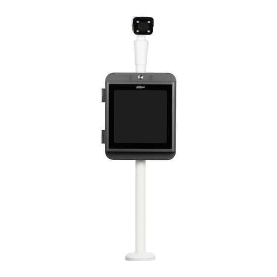
User’s Manual Structure This 2 MP access ANPR kit consists of access ANPR camera, universal joint, and the LED display. The access ANPR camera adopts deep learning intelligent algorithm, and supports various intelligent functions including vehicle detection, LPR (license plate recognition), vehicle logo recognition, vehicle type recognition, vehicle color recognition, H.265 coding, voice broadcast, and displaying vehicle information on LED, and more. - Page 7 User’s Manual Figure 1-2 Base dimensions (mm) Structure Figure 1-3 Access ANPR kit structure...
-
Page 8: Ports
User’s Manual Table 1-1 Access ANPR kit structure Description Description Microphone Speaker Intercom button Access ANPR camera Mainboard Universal joint Wiring board LED display Power Base — — Earth leakage circuit breaker (ELCB) Ports 1.3.1 Control Panel Ports Figure 1-4 Control panel ports Table 1-2 Control panel port description Interface... -
Page 9: Structure
User’s Manual Interface Description IO1, GND, I/O port 2-channel I/O input. IO2, GND A/R, B/T, NC, RS-485\RS-232 Reserved function. Receive 485 or 232 signals, or port connect to laser device, radar, etc. 1.3.2 Earth Leakage Circuit Breaker (ELCB) Ports Figure 1-5 ELCB ports Table 1-3 ELCB port description Port... -
Page 10: Installation
User’s Manual Installation Connecting the Cable Figure 2-1 Connecting the cable Step 1 Align the screwdriver with the screw in the cable slot, and turn the screwdriver counterclockwise to loosen the screw. Step 2 Insert the cable into the corresponding slot. Step 3 Align the screw with the slot, and then turn the screwdriver clockwise to tighten the screw. - Page 11 User’s Manual Figure 2-2 Holes in the base (mm) Step 3 Mount the Kit to the base, and screw the nut into the base to fix the Kit.
-
Page 12: Basic Configuration
User’s Manual Basic Configuration ConfigTool This section is only applicable to the configuration and upgrade of access ANPR camera (hereinafter referred to as "the Camera"). This section only introduces the general operations of quick configuration tool. For details, see ConfigTool User's Manual. - Page 13 User’s Manual Figure 3-1 Modify IP Step 3 Select the uninitialized device. Click Figure 3-2 Device initialization (1) Step 4 Select the device which needs to be initialized. Click Initialize. The interface might be different depending on the model you purchased, and the actual product shall prevail.
- Page 14 User’s Manual Figure 3-3 Device initialization (2) Step 5 Configure the parameters. Table 3-1 Parameter description Parameter Description User Name The user name is admin by default. The new password can be set from 8 characters to 32 characters New Password and contains at least two categories from upper cases, lower cases, numbers and special characters (excluding “'”, “"”, “;”, “:”...
-
Page 15: Modifying Ip Address
User’s Manual 3.1.2 Modifying IP Address 3.1.2.1 Modifying One IP Address Step 1 Click Step 2 Click Search setting. Figure 3-4 Setting Step 3 Configure device segment, enter login user name and password. Click OK. The devices searched will be displayed after searching is completed. Uninitialized devices can be used after initialization. - Page 16 User’s Manual Manual mode: Set Mode as Static, and fill in Target IP, Subnet Mask and Gateway, and then the device can automatically acquire IP address from DHCP server. Step 6 Click OK. 3.1.2.2 Batch Modifying Step 1 Click Step 2 Click Search setting.
-
Page 17: Upgrading Device
User’s Manual DHCP (Dynamic Host Configuration Protocol) mode: When there is DHCP server in the network, set Mode as DHCP, and then the device can automatically acquire IP address from DHCP server. Manual mode: Set Mode as Static, and enter Start IP, Subnet Mask and ... -
Page 18: Logging In To Web
User’s Manual Figure 3-9 Select upgrade file Step 4 Upgrade the device. Upgrade one device: Click Upgrade, and the system starts upgrading. You can see the upgrade progress. Batch upgrade: Click OK, and the system starts upgrading. If the device is disconnected during upgrading, as long as the ConfigTool stays on the upgrade interface, the upgrade will resume when the connection is restored. -
Page 19: Web Configuration
User’s Manual Web Configuration Make sure the Camera is properly installed and powered up. For detailed configuration, see user’s manuals of corresponding Camera. The figures shown in this section are for reference only, and the actual interface shall prevail. -
Page 20: Password Reset
User’s Manual The new password can be set from 8 characters to 32 characters and contains at least two categories from upper cases, lower cases, numbers and special characters (excluding “'”, “"”, “;”, “:” and “&”) If you want to modify the password again, go to Setting > System > Account > ... - Page 21 User’s Manual The Login interface is displayed. See Figure 4-3. Figure 4-3 Login interface Step 2 Click Forgot password? If you use IE browser, the system might prompt Stop running the script, click No and continue to run the script. Figure 4-4 Reset password (1) Step 3...
-
Page 22: Guide
User’s Manual Figure 4-5 Reset password (2) Step 6 Set Password and Confirm Password. The new password can be set from 8 characters to 32 characters and contains at least two categories from upper cases, lower cases, numbers and special characters (excluding “'”, “"”, “;”, “:”... - Page 23 User’s Manual Step 2 Confirm information of Software Version, and then click OK. Figure 4-7 Plate pixel Step 3 You can check whether the video image is properly zoomed and focused by checking the plate pixel. Drag zoom and focus bar to adjust the video image properly. When the vehicle plate comes into the green line area, click Snapshot to take a snapshot of the plate.
-
Page 24: Lattice Screen
User’s Manual Figure 4-9 Recognition Step 4 Configure recognition area. The config example on the right of video image can be used as a reference. Click Iden Area. Click and draw 4 lines on the video image and the recognition area is formed. Click Snap Line. - Page 25 User’s Manual Figure 4-10 Lattice screen config Step 2 Select Lattice Screen State. You can select from Car Pass State and Normal State. The information displayed on the screen may vary in different states. Step 3 Select the display mode from Type One:2*2, Type Two:2*1, and Type Three:4*1. For example, if you select Type Three:4*1, it means an information display area consists of 4 small matrixes from 1 line.
-
Page 26: Broadcast Content
User’s Manual Select one mode, and drag the left mouse button on the screen to redraw the matrix, or click on any small matrix, and the system will automatically generate the matrix based on the mode you selected. After redrawing the matrix, right-click on the redrawn matrix to change the name of the matrix. -
Page 27: Volume/Code Set
User’s Manual Click Remove All to delete all the broadcast items. Step 6 Click Confirm. 4.4.3 Volume/Code Set You can configure the input volume, and the volume and speed of speaker. Step 1 Select Setting > ITC > Voice Broadcast > Volume/Code Set. Figure 4-14 Volume/Code set Step 2... - Page 28 User’s Manual Figure 4-15 Live interface Step 3 Click Figure 4-16 Config (LPR) Step 4 Set focus and zoom mode, which is used to recognize vehicle. Table 4-1 Focus parameter description Parameter Description Auto Focus Auto adjust camera lens and make the scenario clearly focused.
- Page 29 User’s Manual Parameter Description Manually set focus parameter and make the camera focus on the vehicle. Zoom: Step length: There are totally 3 levels to be selected. Zoom in, zoom out: Click and add a step length, click ...
-
Page 30: Faq
Check whether the right upgrade program (such as Network upgrade failed version, compatibility) is used. Dahua 16GB, Dahua 32GB, Dahua 64GB, Kingston 16GB, Kingston 32GB, and Kingston 64GB. It is recommended to Recommended TF card use class 10 high capacity card, which supports max 128G TF card. -
Page 31: Appendix 1 Cybersecurity Recommendations
User’s Manual Appendix 1 Cybersecurity Recommendations Cybersecurity is more than just a buzzword: it’s something that pertains to every device that is connected to the internet. IP video surveillance is not immune to cyber risks, but taking basic steps toward protecting and strengthening networks and networked appliances will make them less susceptible to attacks. - Page 32 User’s Manual Change Default HTTP and Other Service Ports We suggest you to change default HTTP and other service ports into any set of numbers between 1024~65535, reducing the risk of outsiders being able to guess which ports you are using. Enable HTTPS We suggest you to enable HTTPS, so that you visit Web service through a secure communication channel.
- Page 33 User’s Manual The network should be partitioned and isolated according to the actual network needs. If there are no communication requirements between two sub networks, it is suggested to use VLAN, network GAP and other technologies to partition the network, so as to achieve the network isolation effect.
Need help?
Do you have a question about the DHI-IPMECS-2201C and is the answer not in the manual?
Questions and answers