Table of Contents
Advertisement
Quick Links
Advertisement
Table of Contents

Related Manuals for Dahua DHI-ASA2212A


Summary of Contents for Dahua DHI-ASA2212A
- Page 1 Time Attendance User’s Manual V1.0.1...
-
Page 2: Table Of Contents
Table of Contents Table of Contents ...................... 2 Product Overview ..................1 Introduction ..................... 1 Installation Guide ..................1 Checklist ......................1 Panel and Interface ..................1 Appearance Dimensions ................. 4 Installation Wiring .................... 5 System Operation ..................6 Attendance ...................... 6 Main Menu ...................... - Page 3 3.6.3 Bell ...................... 28 System Config ....................30 3.7.1 Set Time and Date ................31 3.7.2 Volume....................32 3.7.3 Restore ....................32 3.7.4 Relay Mode ..................33 3.7.5 Restart Device ..................34 Communication ..................... 34 USB ......................35 3.9.1 Export User Info .................. 35 3.9.2 Firmware Update ................
- Page 4 Important Safeguards and Warnings Please read the following safeguards and warnings carefully before using the product in order to avoid damages losses and body injuries. After reading, please well keep this user's manual. Note: Do not install the device at position exposed to sunlight or in high temperature. ...
- Page 5 Please visit our website for more information. ...
-
Page 6: Product Overview
1 Product Overview Introduction All-in-one time attendance is an attendance device integrating card, fingerprint, config and execution. It is suitable office, commercial building, school and etc. Time attendance functions: Touch button+LCD display, TCP-IP protocol Fixed and flexible attendance mode. ... -
Page 7: Installation Guide
2 Installation Guide Checklist Before installation, please check Name Quantity Note Unit Installation bracket Installation map M4×30 cross pan head flat Used to fix bracket for screw concealed mount Used to fix device from M3×6 inner hex sunk head bottom to installation screw bracket T10 inner hex wrench... -
Page 8: Table Of Contents
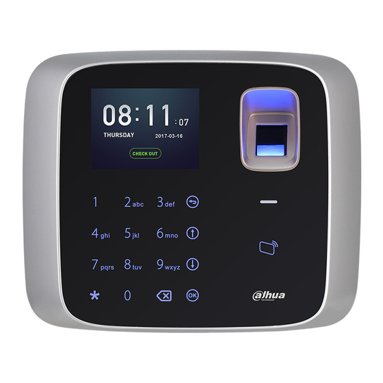
Figure 2-1 Icon Note Number key, for number and letter input 0~9 Return or exit Down Enter or confirm Switch, between function or input Delete Chart 2-2 Figure 2-2... - Page 9 Figure 2-3 Port Note +12VIN DC 12V power PUSH Unlock NC/BELL- Lock NC or BELL(disconnect triggered) COM/BELL+ Lock COM or BELL+ NO/BELL- Lock NO or BELL-(close triggered) Chart 2-3...
-
Page 10: Appearance Dimensions
Appearance Dimensions Figure 2-4... -
Page 11: Installation Wiring
Installation Wiring Figure 2-5 Installation step: Step 1. Paste installation map on installation surface, and open hole according to the map. Insert expansion bolt into the hole. Step 2. Install bracket. If there is concealed mount, fix bracket on concealed mount with screw A. ... -
Page 12: System Operation
3 System Operation Note: Fingerprint record is in Appendix 1. Input of text is in Appendix 2. Attendance Warning: During attendance, please DO NOT change system config, system time or power off the device, since these will cause abnormal attendance. Plug the device to power, device boots up and shows time info, see Figure 3-1. -
Page 13: Main Menu
Figure 3-2 In fingerprint area, press your finger to pass attendance. In card swiping area, swipe card and pass attendance. Click to switch attendance status. Connect to platform and sync status to platform, used on platform. After you pass personal attendance, click , to show personal attendance record, see Figure 3-3 and Figure 3-4. -
Page 14: User
If you have added admin user in User Level (User→ User Level), you can login via fingerprint, card or password. Figure 3-5 Click to select, click or directly enter number below each function. When you insert USB disk, you can see at the upper right corner. - Page 15 Figure 3-6 Figure 3-7 Step 2. Click to select parameter, click to confirm. Enter number into, and click to save. Note: User ID, card, password, department and shift can be edited via number key or backspace. Paramete Note User ID Enter user no., max 11 digits of number.
-
Page 16: Search And Edit User
Paramete Note Departm Click to select preset department. Refer to Ch 3.3.3. Shift Enter preset shift. If you do not enter shift, then attendance depends on shift linked to department. If input shift do not match department linked shift, subject to input shift. Refer to Ch 3.4.1. - Page 17 , password method for attendance. , fingerprint method for attendance. Level. 0 is normal user and 1 is admin. Edit and Delete Single User Click to select user, click , see Figure 3-9. Figure 3-9 Select Edit, click , to edit user.
-
Page 18: New Department
Select to search user by no. 3.3.3 New Department You can create department, and set user group. Different departments can have different shifts. Max department is 30. Step 1. Select User>New Department, click . See Figure 3-11. Figure 3-11 Step 2. - Page 19 Select User>Edit and Delete Department, click . See Figure 3-12. Figure 3-12 Edit and Delete Single Department Click to select department, click , see Figure 3-13. Figure 3-13 Select Edit, click , to edit department. Select Delete, click to delete department.
-
Page 20: Shift
Figure 3-14 Select , click to delete all departments. Select to search department by no. Shift 3.4.1 Set Shift You can add shift, and set attendance time and type, up to 20 shifts. 3.4.1.1 Add Shift Step 1. Select Shift>Shift Setup>Shift, click , see Figure 3-15. - Page 21 Step 2. Click , to switch to function key above, select and click Step 3. Click to select parameter, click to confirm. Enter number and click to save. Parameter Note System auto generated. Shift Name Customize shift name, max 32 characters. Click to switch input method.
- Page 22 Step 1. Select Fixed, click . See Figure 3-17. Figure 3-17 Step 2. Click to select parameter, click to confirm. Parameter Note Period 1 and 2 Set attendance period, as sign in/out period. When sign in/out is within set period, attendance is abnormal, otherwise attendance is normal.
- Page 23 Figure 3-18 Step 2. Click to select parameter, click . Click number key to enter. Parameter Note Full Set required work hour per weekday. Late Set sign in time. So sign in after this time will be record as late. Unit is hour.
- Page 24 Figure 3-20 Step 2. Select week, click and select rest or work. Step 3. Click to save. Monthly Step 1. Select monthly, click . See Figure 3-21. Figure 3-21 Step 2. Select date, click and select rest or work. Step 3. Click to save.
- Page 25 Edit and Delete Single Shift Select Shift setup>Shift, select shift, click . See Figure 3-22. Figure 3-22 Select Edit, click to edit shift. Select Delete, click to delete shift. Delete and Edit All Shifts Click , switch to delete and search buttons above, see Figure 3-23. Figure 3-23 ...
- Page 26 3.4.1.3 Add Holiday You can set holiday period up to 64 periods. All shifts within holiday period will have no attendance. Step 1. Select Shift>Shift Setup>Holiday, click See Figure 3-24. Figure 3-24 Step 2. Click , switch to function key above, click and click .
- Page 27 . See Figure 3-26. Select Shift setup>Holiday, select shift, click Figure 3-26 Select Edit, click to edit holiday. Select Delete, click to delete holiday. Delete and Edit All Holidays Click , switch to delete and search buttons above, see Figure 3-23. Figure 3-27 ...
-
Page 28: Department Shift
3.4.2 Department Shift You can set different shifts for different departments. Each department can select shift accordingly. Step 1. Select Shift>Department Shift, click . See Figure 3-28. Figure 3-28 Step 2. Click to select department ID. Step 3. Click number key to input shift no, click to save. -
Page 29: Data
Figure 3-29 Step 2. Enter recheck time, and when you continuously swipe card within set time, it only recors the first time of card swiping. Step 3. Click Data Warning: Make sure you have inserted USB disk into the device before you export attendance record. -
Page 30: Export 1 Month Logs
Figure 3-31 Step 2. Enter user ID and time. Enter user ID to get corresponding user name. Click to switch to time. YOU can search record of current month and previoud month. After you set, move cursor to user ID or user name. Step 3. -
Page 31: Export 1 Month Exception
Figure 3-32 Step 2. Click to select time, click . Excel file generated will be saved in USB. 3.5.3 Export 1 Month Exception You can export all abnormal attendance records of current month or previous month to USB. Step 3. Select Data>Export 1 Month Exception, click . -
Page 32: Features
Features Enter manin menu, click to select Features, click . Or directly click 6. See Figure 3-34. Figure 3-34 3.6.1 Add User in Batch Enter start no., you can batch add user by swiping card. Step 1. Select Features>Add User in Batch, click . -
Page 33: State Switch
Figure 3-36 Step 3. In card swiping area, swipe card. No. will increase automatically as you swipe more card (auto bound to card no.). When you finish, you can view and edit in User>Edit&Delete User. 3.6.2 State Switch You can set attendance state and time according to actual condition. Set state is mainly applied to platform. -
Page 34: Bell
Chart 3-6 Step 3. Click to save. In standby interface, it shows corresponding time status. 3.6.3 Bell Bell mainly connects external bell, as a bell. When device is in relay mode, set bell and you can set bell ring time, when this time is reached, external bell will ring. See Ch 3.7.4. 3.6.3.1 New Bell The system supports up to 8 bells. - Page 35 3.6.3.2 Edit and Delete Bell You can search bell in system and modify and delete bell. Select Features>Bell setup>Search&Delete Bell, click . See Figure 3-39. Figure 3-39 Edit and Delete Single Bell Select bell, click . See Figure 3-40. Figure 3-40 ...
-
Page 36: System Config
Figure 3-41 Select , click to delete all bells. Select to search bell by ID. System Config You can set system time, volume, restore, relay mode and restart device. Enter main menu, click to delete SysConfig, click . Or directly click number key 7. -
Page 37: Set Time And Date
3.7.1 Set Time and Date 3.7.1.1 Set Date Set system data and time format. Step 1. Select SysConfig>Time&Date>Formatting Setting, click . See Figure 3-43. Figure 3-43 Step 2. Click to select parameter, click to switch, immediately effective. Date: YY-MM-DD, MM-DD-YY, DD-MM-YY. ... -
Page 38: Volume
Figure 3-44 Step 2. Enter device date and time, click 3.7.2 Volume Step 1. Select SysConfig>Volume Setting, see Figure 3-45. Figure 3-45 Step 2. Click to adjust volume. 3.7.3 Restore Warning: Restore device will cause data to be lost, be cautious! You can restore device to default, and you can decide whether to keep user info and log. -
Page 39: Relay Mode
only keep user info and record. Device info and user info will be deleted. Restore default setting (keep user info and log), shift will be deleted. Select SysConfig>Restore, see Figure 3-46. Click to select, and click to confirm. Figure 3-46 3.7.4 Relay Mode Relay mode includes bell, lock and none modes. -
Page 40: Restart Device
3.7.5 Restart Device Select SysConfig>Restart Device, click to restart. Communication When time attendance connects to platform, you shall set device IP address to add device on platform. Before setup, please make sure Ethernet cable is cnnected, and sign is shown on screen. -
Page 41: Usb
Figure 3-49 Step 3. Click to select number position. Enter numberkey, see Chart 3-8. Parameter Note DHCP DHCP(Dynamic Host Configuration Protocol). Enable DHCP, auto get IP address. Now IP address, subnet mask and gateway are not available. IP, Mask, Gateway When DHCP is disabled, you set IP address, mask and gateway. -
Page 42: Firmware Update
Fingerprint info cannot be exported. 3.9.2 Firmware Update Step 1. Copy update file to USB disk, name it “update.bin”, and insert USB disk to device USB port. Step 2. Select USB>Firmware Update, click Step 3. Click again to update. 3.10 System Info You can view user capacity, fingerprint capacity and record capacity plus current usage status. -
Page 43: Daily Operation
4 Daily Operation 1. How to set unlock by device? A: Pass admin verification, select SysConfig>Relay>Unlock set unlock time, click Note: The device only can set unlick time, no door sensor or alarm setup. 2. How to let device support external bell? A: External bell is for purpose of scheduled warning. -
Page 44: Faq
5 FAQ Step 1. Invalid card, cannot pass attendance. A: Confirm if user of the card is added to attendance list. Step 2. Bell cannot work. A: Confirm wiring is normal, meantime make sure relay mode has selected bell. Step 3. I cannot update device via USB. A: Check if USB is recognized, meantime name sure update file is named “update.bin”. -
Page 45: Appendix A Fingerprint Operation
Appendix a Fingerprint Operation Notice Keep your finger clean. When you record finger, place finger flat on collector, make center of finger face center of collector. Recommended Finger Index finger, middle finger and ring finger are recommended for fingerprint collection. See Figure A-0-1. - Page 46 Figure A-0-3...
-
Page 47: Appendix 2 Text Input
Appendix 2 Text Input The device support text input of English, number and symbol. Click to switch. Number Step 1. Click to switch input, see Figure A2-0-1. Figure A2-0-1 Step 2. Enter number, click to confirm, see Figure A2-0-2. Figure A2-0-2 English Step 1. - Page 48 Figure A2-0-5 Step 2. Click number key, enter corresponding symbol. Click to flip page, see Figure A2-6. Figure A2-6 Step 3. Click to confirm. Note: This manual is for reference only. Slight difference may be found in user interface. ...
Need help?
Do you have a question about the DHI-ASA2212A and is the answer not in the manual?
Questions and answers