
Related Manuals for Dahua DHI-ASC3202B


Summary of Contents for Dahua DHI-ASC3202B
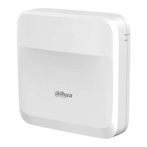
- Page 1 Access Controller Quick Start Guide ZHEJIANG DAHUA VISION TECHNOLOGY CO., LTD. V1.0.4...
-
Page 2: Foreword
Quick Start Guide Foreword General This manual introduces the wiring, installation and basic operations of the Access Controller. Read carefully before using the device, and keep the manual safe for future reference. Safety Instructions The following signal words might appear in the manual. Signal Words Meaning Indicates a high potential hazard which, if not avoided, will result in... - Page 3 Quick Start Guide Privacy Protection Notice As the device user or data controller, you might collect the personal data of others such as their face, audio, fingerprints, and license plate number. You need to be in compliance with your local privacy protection laws and regulations to protect the legitimate rights and interests of other people by implementing measures which include but are not limited: Providing clear and visible identification to inform people of the existence of the surveillance area and provide required...
-
Page 4: Important Safeguards And Warnings
Quick Start Guide Important Safeguards and Warnings This section introduces content covering the proper handling of the Access Controller, hazard prevention, and prevention of property damage. Read carefully before using the Access Controller, and comply with the guidelines when using it. Transportation Requirement Transport, use and store the Access Controller under allowed humidity and temperature conditions. - Page 5 Quick Start Guide Use an adapter or cabinet power supply provided by the manufacturer. ● Use the power cords that are recommended for the region and conform to the rated power ● specifications. The Access Controller is a class I electrical appliance. Make sure that the power supply of the ●...
-
Page 6: Table Of Contents
Quick Start Guide Table of Contents Foreword................................I Important Safeguards and Warnings......................III 1 Dimensions and Appearance.......................... 1 2 Ports Overview..............................4 3 Wiring of Locks...............................11 3.1 Wiring of Magnetic Locks........................11 3.1.1 Wiring of Dual Magnetic Locks with PoE (12 V and Relay).............11 3.1.2 Wiring of Dual Magnetic Locks with 12 V External Power Supply (12 V and Relay).... -
Page 7: Dimensions And Appearance
Quick Start Guide 1 Dimensions and Appearance Figure 1-1 Dimensions (mm [inch]) - Page 8 Quick Start Guide Figure 1-2 Front view Table 1-1 Components description Description Guiding mark Front panel Screw...
- Page 9 Quick Start Guide Figure 1-3 Back cover Table 1-2 Back cover description Description Tamper alarm switch Upper DIN clip Lower DIN clip Wiring outlet...
-
Page 10: Ports Overview
Quick Start Guide 2 Ports Overview Figure 2-1 Ports Table 2-1 Ports description Name Description READER1 Reader connector READER2 Reader connector Auxiliary connector (including door detector, door exit button, and alarm input) DC IN Power connector ALM_OUT Alarm output connector RJ45 Network connector (PoE) —... - Page 11 Quick Start Guide Name Description LOCK Power lock connector STATUS LED indicator RS485 RS485 connector (not used) AUDIO Audio connector (not used) Figure 2-2 Reader connector Table 2-2 Reader connector description Port Description 12 V Supplies 12 VDC power for the reader. Connects the grounding wire.
- Page 12 Quick Start Guide Port Port Name Indicator color Status Solid yellow and green Lock open Lock 2 indicator Solid red Lock closed Lock 1 indicator Solid yellow and green Lock open Figure 2-4 Auxiliary I/O ports Table 2-4 Description of auxiliary I/O ports Ports Description Door detector for door 1...
- Page 13 Quick Start Guide Figure 2-5 Power ports Table 2-5 Description of power ports Ports Description – Grounding wire 12 VDC. For powering the Access Controller when not using Power over Ethernet. Figure 2-6 Alarm output ports...
- Page 14 Quick Start Guide Table 2-6 Description of alarm output ports Ports Description OUT2+ Alarm output 2 OUT2- OUT1+ Alarm output 1 OUT1- Figure 2-7 Relay ports Table 2-7 Description of relay ports Ports Description REL1 Connects to relay devices. Max voltage = +12 VDC; Max load = 500 mA REL2 Connect locks to the pins according to the wiring diagram generated through the hardware configuration.
- Page 15 Quick Start Guide Figure 2-8 Lock ports Table 2-8 Description of lock Ports Description L1/L2 Power one or two locks (DC output). The lock connector can also be used to power external devices. Connects to lock (12 VDC and Max total load = 1000 mA). REL2 Controls up to 12 V lock.
- Page 16 Quick Start Guide Table 2-9 Description of RS-485 Ports Description 485A/485B Reserved port. Not used. Grounding wire. Figure 2-10 Audio ports Table 2-10 Description of audio ports Ports Description MIC+ Reserved port. Not used. MIC- Grounding wire. SPK+ Reserved port. Not used. SPK- Grounding wire.
-
Page 17: Wiring Of Locks
Quick Start Guide 3 Wiring of Locks This section uses lock wiring of two-door solution as an example. The wiring of lock might differ depending on the lock type that you configured. Configure lock for Relay. ● Relay Open = Unlocked: Set the lock to unlock when the relay is open. Relay Open = Locked: Set the lock to remain locked when the relay is open. -
Page 18: Wiring Of Dual Magnetic Locks With 12 V External Power Supply (12 V And Relay)
Quick Start Guide Figure 3-3 Wiring of locks 3.1.2 Wiring of Dual Magnetic Locks with 12 V External Power Supply (12 V and Relay) Supply power for the Access Controller through 12 V external power supply. One door uses the external power supply, and the other uses the Access Controller to supply power. -
Page 19: Wiring Of Dual Magnetic Locks With 12 V External Power Supply (Relay)
Quick Start Guide Figure 3-5 Lock 2 (door 2) 3. Wire the locks according to the diagram below. Figure 3-6 Wiring of locks 3.1.3 Wiring of Dual Magnetic Locks with 12 V External Power Supply (Relay) Supply power for the Access Controller through 12 V external power supply. Both doors use the external power supply. - Page 20 Quick Start Guide Figure 3-7 Lock 1 (door 1) 2. Select Relay Open = Unlocked from the Relay list for lock 2 (door 2). Figure 3-8 Lock 2 (door 2) 3. Wire the locks according to the diagram below. Figure 3-9 Wiring of locks...
-
Page 21: Wiring Of 2-In-1 Magnetic Lock With 12 V External Power Supply (Relay)
Quick Start Guide 3.1.4 Wiring of 2-in-1 Magnetic Lock with 12 V External Power Supply (Relay) Supply power for the Access Controller through 12 V external power supply. Both doors use the external power supply. 1. Select Relay Open = Unlocked from the Relay for lock 1 (door 1). Figure 3-10 Lock 1 (door 1) 2. -
Page 22: Wiring Of Electric Strike Lock
Quick Start Guide Figure 3-12 Wiring of locks 3.2 Wiring of Electric Strike Lock 3.2.1 Wiring of Dual Electric Strikes with PoE Supplies power for the Access Controller over the same Ethernet cable. and the Access Controller supplies power for both locks. 1. -
Page 23: Wiring Of Dual Electric Strikes With 12 V External Power Supply
Quick Start Guide Figure 3-14 Lock 2 (door 2) 3. Wire the locks according to the diagram below. Figure 3-15 Wiring of locks 3.2.2 Wiring of Dual Electric Strikes with 12 V External Power Supply Supply power for the Access Controller through 12 V external power supply, and the Access Controller supplies power for the both locks. - Page 24 Quick Start Guide Figure 3-16 Lock 1 (door 1) 2. Select Fail Secure from the 12V list for door 2. Figure 3-17 Lock 2 (door 2) 3. Wire the locks according to the diagram below.
- Page 25 Quick Start Guide Figure 3-18 Wiring of locks...
-
Page 26: Installation
Quick Start Guide 4 Installation 4.1 Wall Mount Procedure Step 1 Paste the positioning map to the wall at an appropriate position. Step 2 Drill holes through the marks on the map. Step 3 Hammer in the expansion tubes, and then remove the map. Figure 4-1 Hammer in the expansion tubes Step 4 Slide up the front panel of the Access Controller and remove the panel. - Page 27 Quick Start Guide Figure 4-2 Remove the front panel Step 5 Attach the back panel of the Access Controller to the wall with self-tapping screws. Step 6 Wire the Access Controller, bind the wires with nylon cable ties, and then cut off the excess part of the ties.
-
Page 28: Din Rail Mount
Quick Start Guide Figure 4-3 Mount the Access Controller to the wall Step 9 Remove the protection film. 4.2 DIN Rail Mount Procedure Step 1 Attach the DIN rail to the wall with screws. The DIN rail does not come with the Access Controller. Step 2 Hook the lower DIN clip of the back panel onto the bottom of the DIN rail, slightly push upwards the back panel, and then push the back panel backwards to hook the upper DIN... - Page 29 Quick Start Guide Figure 4-4 DIN clips Figure 4-5 Hook DIN clips to the rail Step 3 Slide up the front panel of the Access Controller to remove the cover. Step 4 Wire the Access Controller, bind the wires with nylon cable ties, and then cut off the excessive part of the ties.
- Page 30 Quick Start Guide Step 5 Align the marks on the front panel with the marks on the back panel, and then slide down the front cover to attach it. Figure 4-6 Slide down the front cover Step 6 Screw a screw into the bottom of the Access Controller to secure it. Step 7 Remove the protection film.
-
Page 31: Access Control Configurations
Quick Start Guide 5 Access Control Configurations 5.1 Networking Diagram The main controller comes with a management platform (herein referred as the platform). Sub controller needs to be added to the platform of the main controller. The main controller can manage up to 19 sub controllers. -
Page 32: Initialization
Quick Start Guide 5.2.2 Initialization Initialize the main controller when you log in to the webpage for the first time or after it is restored to its factory defaults. Prerequisites Make sure that the computer used to log in to the webpage is on the same LAN as the main controller. -
Page 33: Logging In
Quick Start Guide The system automatically check is there any higher version available, and inform the user to update the system. The system automatically checks for new updates, and informs you when a new update is available. Step 6 Click Completed. The system automatically goes to the login page after initialization is successful. - Page 34 Quick Start Guide Figure 5-5 Configure door parameters Table 5-1 Parameter description Parameter Description Select the card reader protocol. Wiegand: Connects to a Wiegand reader. You can connect the ● LED wire to the LED port of the controller, and the reader will Entry Card Reader beep and flash when the door unlocks.
- Page 35 Quick Start Guide Parameter Description 12 V: The controller provides power to the lock. ● Fail secure: When the power is interrupted or fails, the door stays locked. Fail safe: When the power is interrupted or fails, the door automatically unlocks to let people leave. Relay: The relay supplies power for the lock.
- Page 36 Quick Start Guide Parameter Description The Bluetooth card must be a certain distance away from the access control device to exchange data and unlock the door. Following are the ranges that are most suitable for it. Short-range: The Bluetooth unlock range is less than 0.2 m. ●...
- Page 37 Quick Start Guide A wiring diagram is generated based on your configurations. You can wire the device according to the diagram. The image below is for reference only. Figure 5-8 Wiring diagram Step 10 Click Apply. You can go to Local Device Config > Hardware to change the settings after you ●...
-
Page 38: Adding Devices
Quick Start Guide Related Operations If you want to change the settings of the hardware, go to Local Device Config > Hardware. 5.2.4 Adding Devices You can add devices to the management platform of the main controller in batches or one by one. If the controller was set to the main controller while you were going through the login wizard, you can add and manage sub controllers through the Platform. - Page 39 Quick Start Guide The added controllers are displayed on the Device Management page. Figure 5-10 Successfully add devices If the controller was set as the main controller while you were going through the login wizard, the controller will be added to the management platform automatically and function as both the main controller and sub controller.
-
Page 40: Adding Users
Quick Start Guide Figure 5-11 Auto search All devices that were searched for will be displayed. You can select devices from the list, and click Device Initialization to initialize them in batches. To ensure the security of devices, initialization is not supported for devices on different segments. - Page 41 Quick Start Guide To prevent data loss caused by force majeure damage to the equipment, it is recommended to regularly export user data for backup purposes. Import users: On the Person Management page, click Download Template, enter user ● information in the template, and then click Import to import all users. Extract all the users: On the Person Management page, click More >...
- Page 42 Quick Start Guide 1. Click 2. Enter the name of the role, and then click Add. 5.2.5.3 Configuring Basic User Information Procedure Step 1 On the home page, select Person Management. Step 2 Add users. Add users one by one. ●...
- Page 43 Quick Start Guide Parameter Description The type of user. General User : General users can unlock the door. VIP User : When the VIP unlocks the door, service personnel will receive a notice. Guest User : Guests can unlock the door within a defined period or for a set number of times.
- Page 44 Quick Start Guide Figure 5-14 Quick add 3. Select the department, role and the effective time. 4. Issue cards to the users in batches. You can manually enter the card number, or use the enrollment reader or card reader to read the card number. For details, see "5.2.5.4.2 Adding Cards". Related Operations Batch Edit: Edit personal information in batches.
- Page 45 Quick Start Guide Figure 5-15 Batch edit 5.2.5.4 Adding Authentication Methods Add password, cards, fingerprint or Bluetooth cards to users, so that users can unlock the door through authentication. Each user can have up to 1 password, 5 IC/ID cards, 3 fingerprints, and 5 Bluetooth cards.
- Page 46 Quick Start Guide Figure 5-16 Add the password If Pin code authentication is not enabled, you can unlock the door by entering the ● unlock password in the format of user ID#password# . For example, if the user ID is 123, and the password you set is 12345, and then you must enter 123#12345# to unlock the door.
- Page 47 Quick Start Guide Enter the card number manually. ● 1. Click Add. 2. Enter the card number, and then click Add. Use the enrollment reader to read the card number. ● Figure 5-17 Use the enrollment reader to read the card number 1.
- Page 48 Quick Start Guide Figure 5-18 Use the card reader to read the card number 1. Click Modify, and then select a card reader. Make sure that the card reader is connected to the Access Controller. 2. Click Read Card, and then swipe the cards on the card reader. A 60-second countdown is displayed to remind you to swipe the card, and the system will read the card number automatically.
- Page 49 Quick Start Guide Figure 5-19 Issue cards through the enrollment reader or card reader Related Operations : Change the number of the card. ● : Set the card to duress card. ● An alarm is triggered when people use the duress card to unlock the door. : Delete the card.
- Page 50 Quick Start Guide Step 2 Connect a fingerprint scanner to the computer, and follow the on-screen instructions to register the fingerprint. Step 3 Click Add. 5.2.5.4.4 Adding Bluetooth Cards Add Bluetooth cards to users for them to gain access through Bluetooth cards. Prerequisites The Bluetooth unlock function has been turned on.
- Page 51 Quick Start Guide Figure 5-20 Flowchart for configuring Bluetooth unlock Procedure On the tab, click Bluetooth Card. Step 1 3 methods are available to add Bluetooth cards.
- Page 52 Quick Start Guide Request through Email one by one: Click Request through Email. ● A Bluetooth card is generated automatically. You can generate up to 5 cards for each user. Figure 5-21 Request through Email Request through Email in batches. ●...
- Page 53 Quick Start Guide Figure 5-22 Batch issue cards If you have requested Bluetooth cards for the user before, you can add the Bluetooth ● cards through registration code. using registration codes. Figure 5-23 The flowchart for requesting through registration code 1.
- Page 54 Quick Start Guide 3. On the Bluetooth Card tab, click Request through Registration Code, paste the registration code, and then click OK. Figure 5-24 Request through registration code 4. Click OK. The Bluetooth card is added. Click OK. Step 2 Results After users sign up and log in to DMSS with the Email address, they can open DMSS to unlock the door through Bluetooth cards.
- Page 55 Quick Start Guide Figure 5-25 Unlock the door through Bluetooth cards Related Operations Users can manage Bluetooth cards on DMSS. ● Move to the Top: If multiple Bluetooth cards have been added, you can move cards to the top that are currently in use. Rename: Rename the Bluetooth card.
-
Page 56: Adding Weekly Plans
Quick Start Guide View the request records: On the Person Management page, click More > Bluetooth Card ● Records to view the request status. Figure 5-26 Request status View Details: View the details of the request, including user information, reasons for failed requests and more. -
Page 57: Adding Areas
Quick Start Guide Figure 5-27 Create the weekly plan Step 3 Drag the slider to adjust the time period for each day. You can also click Copy to apply the configured time period to other days. You can only configure up to 4 time sections for each day. Step 4 Click Apply. -
Page 58: Adding Permission Rules
Quick Start Guide Figure 5-28 Add areas Step 3 Enter the name of the area. Step 4 Select doors. Click Apply. Step 5 5.2.8 Adding Permission Rules By creating permissions rules, you can assign access permissions to users by linking them to the areas. - Page 59 Quick Start Guide Dept: All personnel in the department will be assigned with access permissions. ● Role: All personnel with these roles will be assigned with access permissions. ● User: Only selected users will be assigned with access permissions. ● When you want to assign permission to a new person or change access permissions for an existing person, you can simply add the user in a existing department or link them with a existing role, they will be automatically assigned access permissions set...
-
Page 60: Viewing Authorization Progress
Quick Start Guide Figure 5-31 Add area In the Time Templates area, select the weekly plan and the holiday plan. Step 6 Step 7 Click Apply. Related Operations 5.2.9 Viewing Authorization Progress After you assign access permissions to users, you can view the authorization process. Procedure On the home page, select Access Control Config >... -
Page 61: Configuring Global Alarm Linkages (Optional)
Quick Start Guide 5.2.10 Configuring Global Alarm linkages (Optional) You can configure global alarm linkages across different Access Controllers. Procedure Select Access Control Config > Global Alarm Linkage. Step 1 When you have configured both global alarm linkages and local alarm linkages, and if ●... -
Page 62: Configuring Cloud Service
Quick Start Guide Figure 5-34 Door linkage (1) 3. Click Enable to turn on the door linkage function. Figure 5-35 Door linkage (2) If you turn on link fire safety control, all door linkages will automatically change to the Always Open status, and all the doors will open when the fire alarm is triggered. 4. - Page 63 Quick Start Guide Procedure On the home page, select Local Device Config > Network Setting > Cloud Service. Step 1 Step 2 Turn on the cloud service function. The cloud service function is turned on by default. Figure 5-36 Cloud service Click Apply.
-
Page 64: Configurations Of Sub Controller
Quick Start Guide 5.3 Configurations of Sub Controller You can log in to the webpage of the sub controller to configure it locally. 5.3.1 Initialization Initialize the sub controller when you log in to the webpage for the first time or after the sub controller is restored to its factory default settings. -
Page 65: Appendix 1 Security Commitment And Recommendation
Dahua employees and provide adequate security for products. Dahua has established a professional security team to provide full life cycle security empowerment and control for product design, development, testing, production, delivery and maintenance. - Page 66 Quick Start Guide Service Configuration 1. Enable HTTPS It is recommended that you enable HTTPS to access Web services through secure channels. 2. Encrypted transmission of audio and video If your audio and video data contents are very important or sensitive, we recommend you to use encrypted transmission function in order to reduce the risk of your audio and video data being eavesdropped during transmission.
- Page 67 Quick Start Guide By viewing logs, you can learn about the IP addresses that attempt to log in to the device and key operations of the logged users. 3. Configure network log Due to the limited storage capacity of devices, the stored log is limited. If you need to save the log for a long time, it is recommended to enable the network log function to ensure that the critical logs are synchronized to the network log server for tracing.
Need help?
Do you have a question about the DHI-ASC3202B and is the answer not in the manual?
Questions and answers