Table of Contents
Advertisement
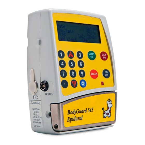
Service Manual
for
BodyGuard 323, 545, & 575
Infusion pumps
0344
Manufacturer:
Caesarea Medical Electronics Ltd.
International Toll Free: +800-323-575-00
European address:
Staufenburgstr. 23 Lichtenstein
P.o.b. 1248 Lichtenstein 72805 Germany
E-mail: sales@cme-infusion.com
www.cme-infusion.com
PN 100-091X ver. 191009
Advertisement
Table of Contents


Need help?
Do you have a question about the BodyGuard 323 and is the answer not in the manual?
Questions and answers