ITT GOULDS PUMPS 3935 Installation, Operation And Maintenance Instructions
Hide thumbs
Also See for GOULDS PUMPS 3935:
Table of Contents
Advertisement
Quick Links
Advertisement
Table of Contents

Related Manuals for ITT GOULDS PUMPS 3935


Summary of Contents for ITT GOULDS PUMPS 3935
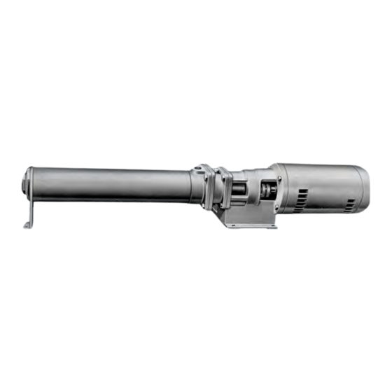
- Page 1 Installation, Operation and Maintenance Instructions Model 3935...
-
Page 3: Table Of Contents
Table of Contents Table of Contents 1 Safety.................................. 3 1.1 Important Safety Notice..........................3 1.2 Safety Warnings ............................3 1.3 Safety ................................ 4 1.4 General precautions ..........................5 ................................. 8 1.6 Parts ................................9 2 Introduction..............................10 2.1 Introduction.............................. 10 3 General ................................ - Page 4 Table of Contents 9 Spare parts............................... 33 9.1 Ordering spare parts ..........................33 9.2 Instructions for ordering spare parts......................33 Model 3935 Installation, Operation and Maintenance Instructions...
-
Page 5: Safety
ITT Goulds pumps will provide safe, trouble-free service when properly installed, maintained, and operat- Safe installation, operation, and maintenance of ITT Goulds Pumps equipment are an essential end user responsibility. This Pump Safety Manual identifies specific safety risks that must be considered at all times during product life. -
Page 6: Safety
Trapped liquid can rapidly expand and result in a violent explosion and injury. ITT Goulds Pumps will not accept responsibility for physical injury, damage, or delays caused by a failure to observe the instructions for installation, operation, and maintenance contained in this Pump Safety Manual or the current IOM available at http://www.gouldspumps.com/literature. -
Page 7: General Precautions
Personal injuries will result if procedures outlined in this manual are not followed. ITT Goulds Pumps will not accept responsibility for physical injury, damage or delays caused by a failure to observe the instructions in this manual and the IOM provided with your equip- ment. - Page 8 Lift equipment only at specifically identified lifting points or as instructed in the current IOM. Current manuals are available at www.gouldspumps.com/literature_ioms.html or from your local ITT Goulds Pumps sales representative. Note: Lifting devices (eyebolts, slings, spreaders, etc.) must be rated, selected, and used for the entire load being lifted.
- Page 9 1.4 General precautions WARNING Make sure to properly lubricate the bearings. Failure to do so may result in ex- cess heat generation, sparks, and / or premature failure. CAUTION The mechanical seal used in an ATEX classified environment must be proper- ly certified.
- Page 10 Maintenance manual (IOM) can cause serious personal injury or damage to the equipment. This in- cludes any modification to the equipment or use of parts not provided by ITT Goulds Pumps. If there is any question regarding the intended use of the equipment, please contact an ITT Goulds representative before proceeding.
-
Page 11: Parts
The code classification marked on the equipment must be in accordance with the specified area where the equipment will be installed. If it is not, do not operate the equipment and contact your ITT Goulds Pumps sales representative before proceeding. -
Page 12: Introduction
2 Introduction 2 Introduction 2.1 Introduction This instruction manual is intended to assist those involved with the installation, operation, and mainte- nance of Goulds Model 3935 Multi-Stage Pumps. It is recommended that this manual be thoroughly reviewed prior to installing or performing any work on the pump or motor. -
Page 13: General
3 General 3 General 3.1 Importance of instructions The design, material, and workmanship incorporated into the construction of Goulds pumps make them capable of giving long, trouble-free service. The life and satisfactory service of any mechanical unit, however, are enhanced and extended by correct application, proper installation, periodic inspection, and careful maintenance. -
Page 14: Installation
4 Installation 4 Installation 4.1 Location Pumping unit should be placed as close as practical to the source of supply. Floor space and head room allotted to the unit must be sufficient for inspection and maintenance. Be sure to allow for crane or hoist service. -
Page 15: Alignment Procedures
4.4 Alignment procedures 4.4 Alignment procedures Pumps which have NEMA C-flange motors directly mounted to the bearing frame do not require pump and motor shaft alignment. Jog motor to be sure rotation is correct before connecting coupling. Rotation is counter-clockwise when viewed from the coupling end. 4.5 Mechanical seals The pump is equipped with a mechanical seal. -
Page 16: Operation
5 Operation 5 Operation 5.1 Start-up ■ Check List Lubrication - J and S Frames J Frame - J frame pumps have a greased-for-life ball bearing. No additional lubrication is required. S Frame - S frame pumps have ball bearings which are greased at the factory. Bearings should be regreased every 2000-3000 hours (3-4 months). - Page 17 5.1 Start-up 1. Oil level 2. Side connection 3. 1/4" nipple-elbow assembly 4. Bearing frame 5. Initial setting for internal adjuster. Figure 2: Dimensional checks Fill bearing reservoir using oiler bottle. Several fillings will be required. Never fill the frame through the frame breather located at the top of the frame or through the oiler without use of the bottle.
-
Page 18: Operational Checks
5.2 Operational checks Be sure suction valve is fully open. Normally, discharge valve should be at least partially closed so that flow will be controlled. Rotation Check With motor uncoupled from frame, jog motor to check for proper rotation. Rotation should be counter-clockwise when viewed from coupling end. Recouple when satisfied. Start Pump is now ready to start. -
Page 19: Preventive And Corrective Maintenance
6 Preventive and corrective maintenance 6 Preventive and corrective maintenance 6.1 Lubrication Refer to 5.1 Start-up on page 14 for lubrication procedures for pump. Follow motor and coupling manu- facturer's lubrication instructions. 6.2 Mechanical seal The seal requires no attention other than to make sure that circulating lines, where installed, do not be- come clogged. -
Page 20: Disassembly And Reassembly
7 Disassembly and reassembly 7 Disassembly and reassembly 7.1 Disassembly of pump Lock out power source. Shut off valves controlling flow to and from pump. Disconnect piping. Drain pump through plug (408A) in bottom of casing adapter. NOTICE: If pump has handled corrosive liquids, the motor end should be elevated to assure complete draining. -
Page 21: Inspection And Overhaul
7.2 Inspection and overhaul 19. Unbolt and remove seal housing (159) from bearing frame. (228 or 228A). 20. Unbolt and remove thrust bearing end cover (109 or 109A). On J frame thrust bearing, cover is not used. Remove retaining ring (361E). 21. -
Page 22: M, L, X, And Y Frames
7.5 M, L, X, and Y frames Refer to lubrication instructions in 5.1 Start-up on page 14 to lubricate the bearings. Replace coupling hub (233) and key (400). 7.5 M, L, X, and Y frames Clean the frame (228A) and bearing end cover (109) and install the oil seals (332A, S33D) with the lips in. - Page 23 7.6 Reassembly of liquid end Slide rotary unit of mechanical seal (383A) over splined end of pump shaft (122) and against retain- ing ring (361D). Use care to avoid cutting rubber bellows on spline teeth. On BP20 pumps, the me- chanical seal shoulders against the step in shaft.
- Page 24 7.6 Reassembly of liquid end Figure 4: Dial indicator Model 3935 Installation, Operation and Maintenance Instructions...
-
Page 25: Bearing And Seal Replacement
7.7 Bearing and seal replacement 14. Continue adding diffusers and impellers. Shim each impeller to obtain the required front clearance. 15. Install spacer sleeves (157) after last impeller has been installed and its Front Clearance is set. Check space between end of last spacer sleeve (157) and snap ring groove at end of shaft. Add shims as necessary under the last spacer (157) until end of spacer covers approximately ½... - Page 26 7.7 Bearing and seal replacement Table 4: BP20 impeller stack clearance BP20 Impeller Stack Required Front Clearance 1st stack + 1.016mm ± 0.127mm | + 0.040" ± 0.005" 14 stages or less 2nd stack + 0.635mm ± 0.127mm | + 0.025" ± 0.005" 15th to 28th stages 3rd stack + 0.889mm ±...
- Page 27 7.7 Bearing and seal replacement Table 6: BP70 impeller stack clearance BP70 Impeller Stack Required Front Clearance 1st stack +1.016mm ± 0.127mm | +0.040" ± 0.005" 1O stages or less 2nd stack +0.508mm ± 0.127mm |+0.020" ± 0.005" 11th to 20th stages 3rd stack +0.508mm ±...
- Page 28 7.7 Bearing and seal replacement Table 8: BP200 impeller stack clearance BP200 Impeller Stack Required Front Clearance 1st stack 4 stages +1.016mm ± 0.127mm | +.040" ±.005" 2nd stack +1.016mm ± 0.127mm | +.040" ±.005" 5th to 8th stages 3rd stack +1.016mm ±...
-
Page 29: Sectional View
7.8 Sectional view 7.8 Sectional view J Frame S Frame M Frame A greased-for-life medium duty Two angular contact bearings A single angular contact bearing carries Conrad bearing carries thrust mounted face-to-face carry low to medium to heavy thrust loads and provides loads developed by the low pres- medium duty thrust loads in this re- oil lubrication for pumps requiring NEMA... -
Page 30: Parts List And Materials Of Construction
7.9 Parts list and materials of construction 7.9 Parts list and materials of construction Table 9: Power End Grease Lubrica- Oil Lubrication Item tion Part Name Material Bearing end cover Cast iron 109A Bearing end cover Cast iron 109C Bearing end cover ra- Cast iron dial Ball bearing, thrust... - Page 31 7.9 Parts list and materials of construction Grease Lubrica- Oil Lubrication Item tion Part Name Material Gasket end cover Vellumoid 361E Retaining ring - bear- Steel 370B H cap screw, frame to Steel ▲Y adapter (not shown) 370N H cap screw - end cov- Steel H cap screw - frame to Steel...
-
Page 32: Pressure/Temperature Capability
7.10 Pressure/temperature capability Item No. Part Name Material 383A Rotary element 18-8 SS-Viton 383B* Stationary seat (XP171) NI-Resist and Viton 383B Stationary seat (XP1D1) Carbide and Viton 408A Pipe plug - drain Brass 412J* O-ring cooling jacket (not shown) Viton 412K O-ring casing Viton... -
Page 33: Trouble Shooting
8 Trouble shooting 8 Trouble shooting 8.1 Troubleshooting Problem Possible causes and correction A. No Liquid delivered, not enough liquid 1, 2. 3. 4, 5, 6, 7. 8, 9, 10, 11, 12, 13, 14, 17, 22, 23 delivered, or not enough pressure B. - Page 34 8.1 Troubleshooting Incorrect bearing frame oil level (high or low) or lack of grease: follow lubrication instructions. Model 3935 Installation, Operation and Maintenance Instructions...
- Page 35 9 Spare parts 9 Spare parts 9.1 Ordering spare parts To ensure against possible long and costly downtime periods, especially on critical services. it is advisa- ble to have spare parts on hand. The most desirable parts to have on hand are the following: Ball Bearings.
- Page 36 9.2 Instructions for ordering spare parts Pump Type GPM @ BEP Number of stages Pump Frame (1) Pump Construction Mechanical Seal Cooling Option (2) Stationary Seat Option (3) Figure 6: Example The first letter of this group (X) indicates the pump frame, the second letter indicates the coupling and stub shaft combination.
- Page 37 Visit our website for the latest version of this document and more information: www.gouldspumps.com ITT Goulds Pumps 240 Fall Street Senenca Falls, NY 13148 Form IOM.3935.en-US.2022-12 ©2022 ITT Corporation The original instruction is in English. All non-English instructions are translations of the original instruction.
Need help?
Do you have a question about the GOULDS PUMPS 3935 and is the answer not in the manual?
Questions and answers