Table of Contents
Advertisement
Visi n
E N G I N E E R I N G
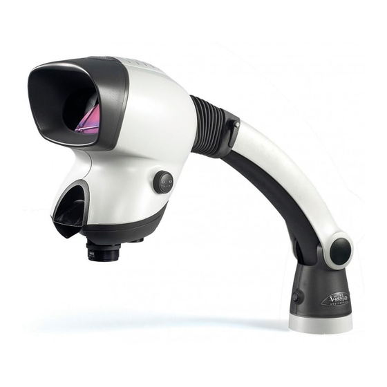
Mantis Stereo Viewing System
Use this manual only after assembling the Mantis Viewing system.
After assembling the Mantis Stereo Viewing System you should be familiar with its various
components. These instructions will help you become familiar with the operation and use of the
Mantis as well as some of the available options. Also included in this manual is a more
comprehensive maintenance, troubleshooting and service guide.
NOTE: REFER TO THE MANTIS USER GUIDE AS REQUIRED
Operating Instructions
And
Service Manual
1/Mantis/7/98
Advertisement
Table of Contents

Related Manuals for Vision Engineering Mantis


Summary of Contents for Vision Engineering Mantis
- Page 1 After assembling the Mantis Stereo Viewing System you should be familiar with its various components. These instructions will help you become familiar with the operation and use of the Mantis as well as some of the available options. Also included in this manual is a more comprehensive maintenance, troubleshooting and service guide.
-
Page 2: Table Of Contents
1) System Diagrams ………………………………………………………………….. Mantis Universal Boom Mount…………………………………………………….. Mantis FX Bench Mount……………………………………………………………. 1) The Basic Systems …….…………………………………………………………. 1) Objective Specifications …………………………………………………………. 1) Using the Mantis ……………..……………………………………………………. Turning the Power “ON” …………..……………………………………………….. Focusing ………….…………………………………………………………………. Adjusting the Lighting ……………………………… …..……………………….… Changing the Magnification ……………………………………………………….. -
Page 3: System Diagrams
SYSTEM DIAGRAMS... -
Page 4: Mantis Universal Boom Mount
Visi n E N G I N E E R I N G MANTIS UNIVERSAL BOOM MOUNT Description User Guide Des. Part No. 1. Yaw Bolt Cover Cover Plate 187-A-0079 2. Yaw Bolt Assembly Yaw Spigot YB-A-001 3. Anti-glare Shield... -
Page 5: Mantis Fx Bench Mount
Visi n E N G I N E E R I N G MANTIS FX BENCH STAND Description User Guide Des. Part No. 1. Yaw Bolt Cover Cover Plate 187-A-0079 2. Yaw Bolt Assembly Yaw Spigot YB-A-001 3. Anti-glare Shield... -
Page 6: The Basic Systems
The Basic Systems... - Page 7 Long working distance offers ample room for rework and part rotation. Mantis systems are available in two versions. One version is the boom mount (refer to page 3 of this manual) which can be mounted on almost any table surface. This is good for general inspection, viewing and rework, especially in a production environment.
-
Page 8: Objective Specifications
Objective Specifications 3) Objective Specifications... - Page 9 The Mantis objectives provide different levels of magnification ranging from 2X to 10X. As magnification changes, working distance (the distance between the objective lens and the subject when properly focused), field of view (the area of subject that is visible in the viewing screen at any one time) and depth of field (the maximum subject height variation that will remain in focus) also change.
-
Page 10: Using The Mantis
Using the Mantis 4) Using the Mantis... -
Page 11: Turning The Power "On
Boom Mount (refer to page 3 of this manual) There is one power switch for the Mantis boom mount system. It is located on the front panel of the vertical support column. Flip the switch to energize the Mantis illuminator FX Bench Stand (refer to page 4 of this manual) There are three power switches for the Mantis FX bench stand system. -
Page 12: Changing The Magnification
Objective lenses are screwed onto the threaded turret underneath the Mantis viewing head. After two objectives have been selected and screwed into place on the Mantis turret, they can be switched using the objective selection lever. The lever is located on the left side of the Mantis viewing head. -
Page 13: Options
Options 5) Options Lens Protective covers... -
Page 14: Lens Protective Covers
All mantis objectives can be fitted with a replaceable, clear plastic protective cap. These inexpensive caps protect the objective lens from damage and are especially useful when using the Mantis for rework operations. Choose from the chart below. Lens Vision Engineering Part No. -
Page 15: Maintenance
Maintenance 6) Maintenance Lamp Replacement (refer to pages 3 or 4 of this manual) -
Page 16: Lens Cleaning
1) Remove the Mantis viewing head by removing the Yaw Spigot nut. 2) Turn the Mantis viewing head upside down. 3) Remove the lamp cover (filter tray) by sliding it away from the Mantis head. Do not allow the diffuser lens to drop when removing the lamp covers. -
Page 17: Troubleshooting
Troubleshooting 7) Troubleshooting Mantis has no power... -
Page 18: Mantis Has No Power
If the Mantis head has no power and the illuminator will not come “ON” then check the following items: Is the Mantis power cord plugged in? • Is the wall outlet functioning properly and supplying sufficient voltage? • Is the fuse in the Mantis support column in good working condition? •... -
Page 19: Service
Service 8) Service... -
Page 20: Cleaning The Mirrors
Cleaning the mirrors The mirrors within the Mantis viewing head can be cleaned. These mirrors are very delicate and can only be blown off with clean, dry air. Never wipe the mirrors with any type of cloth. Required Tools:... - Page 21 Work in a dust free environment 1. Remove the objective lenses. 2. Remove the Mantis viewing head from its support by removing the Yaw bolt. 3. Rest the Mantis viewing head upside down (turret facing “UP”) 4. Remove the three screws from the turret.
-
Page 22: Repairing Eye Spacing Adjustment
Remove Mirror from Mantis Head In the event that a mirror become dislodged within the Mantis viewing head it may be possible to reattach it by following these steps. If a repair cannot be made then follow these steps to... -
Page 23: Mirror Removal
Medium Phillips head screwdriver (magnetic preferred) Work in a dust free environment 1. Remove the Mantis viewing head from its support by removing the Yaw bolt. 2. Rest the viewing head upside down (turret facing “UP”). 3. Remove the two screws on the rear of the viewing head. -
Page 24: Warranty
Warranty 9) Warranty This product is warranted to be free from defects in material and workmanship for a period of one year from the date of invoice to the original purchaser. - Page 25 Vision Engineering Inc. or elsewhere, all at the option of Vision Engineering Inc. However, Vision Engineering Inc. reserves the right to refund the purchase price if it is unable to provide replacement, and repair is not commercially practicable or cannot be timely made.
-
Page 26: Information
Information 10) Information Vision Engineering Inc. is committed to providing top quality optical inspection systems. We employ a staff of trained Sales and Service engineers and have a network of Authorized distributors to assist you. Please call whenever you have questions. - Page 27 Corporate Headquarters Western Region Sales Office Vision Engineering Inc. Vision Engineering Inc. 570 Danbury Road 745 W. Taft Avenue New Milford, CT 06776 Orange, CA 92865 Phone: (860) 355-3776 Phone: (714) 974-6966...
Need help?
Do you have a question about the Mantis and is the answer not in the manual?
Questions and answers