
Related Manuals for ELECRAFT KRX3


Summary of Contents for ELECRAFT KRX3
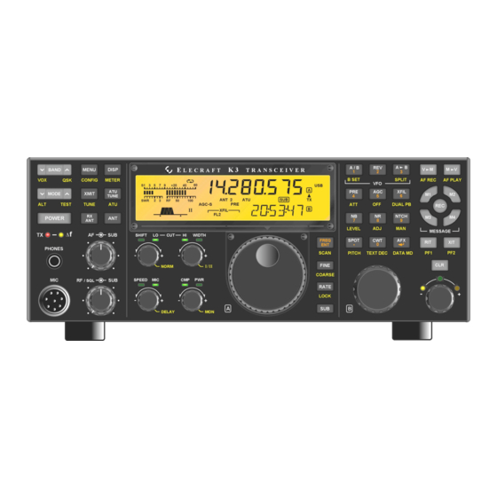
- Page 1 LECRAFT 160 – 6 M ERFORMANCE ETER RANSCEIVER KRX3 ERFORMANCE UBRECEIVER NSTALLATION AND PERATION Rev. E, July 6, 2010 Copyright © 2010, Elecraft, Inc. All Rights Reserved...
-
Page 2: Table Of Contents
Contents See Appendix A to install or change crystal filters in a previously assembled KRX3 Introduction ............................... 3 Customer Service and Support ..........................4 Technical Assistance ............................4 Repair / Alignment Service ..........................4 Preventing Electrostatic Discharge Damage .................... 5 How ESD Damage Occurs .......................... -
Page 3: Introduction
Introduction If your KRX3 is already installed in your K3, turn to Using the Sub Receiver on page 44 for operating instructions. The KRX3 subreceiver features specifications identical to the main K3 receiver including up to five roofing filters and an independent, dedicated DSP system. The subreceiver can tune the same range of frequencies as the main receiver, including frequencies outside of the Amateur bands when it is equipped with the optional KBPF3 general coverage filter board. -
Page 4: Customer Service And Support
Repair / Alignment Service (We want to make sure everyone succeeds!) If necessary, you may return your Elecraft product to us for repair or alignment. (Note: We offer unlimited email and phone support to get your kit running, so please try that route first as we can usually help you find the problem quickly.) -
Page 5: Preventing Electrostatic Discharge Damage
Preventing Electrostatic Discharge Damage There is no climate or work location where the components of your K3 are safe from Electrostatic Discharge (ESD) unless you take specific steps to prevent such damage. Many of the components in your K3 can be damaged by static discharges of only a few volts: far too little for you to notice. -
Page 6: Preparing For Installation
We strongly recommend you take the following anti-static precautions (listed in order of importance) to avoid trouble: Leave ESD-sensitive parts in their anti-static packaging until you install them. The packaging may be a special plastic bag or the component’s leads may be inserted in conductive foam. Parts which are especially ESD-sensitive are identified in the parts list and in the assembly procedures. -
Page 7: Parts Included
Parts Included The following parts should be included in your kit. Check to ensure you have them all. If any parts are damaged or missing, contact Elecraft for replacements (see page 4). Circuit Boards and Enclosure Note: Some pins on the male connectors may have been removed and some holes in the female connectors may have been plugged. -
Page 8: Krx3 Hardware Bag E850334
ELECRAFT ILLUSTRATION DESCRIPTION QTY. PART NO. KNB3 SUBIN Board E850331 ESD Sensitive. KNB3 SUBOUT Board E850332 KRX3 Enclosure, Top (with tall standoffs) E100334 KRX3 Enclosure, Bottom (with short E100334 standoffs) KRX3 Hardware Bag E850334 ELECRAFT ILLUSTRATION DESCRIPTION QTY. PART NO. -
Page 9: E850344 Tmp-Bnc Cable Bag
ELECRAFT ILLUSTRATION DESCRIPTION QTY. PART NO. Standoff, Hex Male/Female, 7/16” (11mm) E700017 Unthreaded Sleeve Spacer, 7/8” (22 mm) E700161 Screw, Zinc, Pan Head 4-40 1/4” (6.8mm) E700005 Screw, Zinc, Pan Head 4-40 1/2” (13 mm) E700196 Screw, Black, Pan Head, 4-40, 1/2” (13 mm) E700030 Screw, Black, Pan Head, 4-40, 3/16”... -
Page 10: E850249 I.f. Crystal Filter Bag (Or Box)
E850249 I.F. Crystal Filter Bag (or Box) NOTE: If the optional 8-pole 2.8K filter is purchased instead (see next item) this filter is not supplied. ELECRAFT ILLUSTRATION DESCRIPTION PART NO. KFL3A-2.7K Filter Note: This filter is not supplied if you E850249 purchased the optional 8-pole 2.8 kHz... -
Page 11: Installation Procedure
Installation Procedure K3 KIT BUILDERS: If you were directed here to install the KRX3 Subreceiver as part of the initial K3 assembly, remove the top cover as shown below, and then go directly to Checking and Modifying Resistor R91 on page 21 since you have already installed the Auxiliary DSP board. -
Page 12: Installing The Auxiliary Dsp Board
If your K3 has the K144XV 2-meter option installed, remove the three 6-32 black flat head screws holding it to the left side panel (see Figure 4). Unplug the cables going to the K144XV module. The red power wire plugs into the K3’s main RF board. Unplug it and set it aside with the module. Figure 4. - Page 13 Remove the screw shown in Figure 6. It is located directly behind the front panel microphone connector. There may be a lock washer under the screw. If so, save it with the screw. Removing the screw ensures the pc boards on the front panel assembly will have adequate clearance when the front panel assembly is removed in a later step.
- Page 14 CAUTION: Before continuing on with the next step, be sure you have removed the three top Front Panel Assembly screws shown in Figure 7. You may bend and damage the front panel or shield assemblies if the screws are not removed! Use a screwdriver in the pry tool openings to press back against the circuit board while pushing the lip on the front panel assembly toward the front as shown in Figure 9.
- Page 15 With the three screws removed, the main DSP board is held on to the front panel board by two multi-pin connectors. Slip your finger tips between the boards and pull the main DSP board away from the front panel board to unplug it. A large, thick spacer washer should be lying on the front panel near the hole for the phones jack (see Figure 12).
- Page 16 Check to see if the nylon standoff shown below near J51 is mounted on the main DSP board. If not, install the nylon standoff supplied with your KRX3 parts as shown below. Be sure you place it in the correct hole near the corner of the board.
- Page 17 Locate resistor R3 on the front panel board (the board still mounted on the front panel assembly). If R3 is positioned above the board on its leads as shown in Figure 16, push it over to one side of the outline as shown. Be sure you don’t push it so far its leads might touch the solder pads for other components on the board.
- Page 18 Plug the aux DSP board into the main DSP board by mating P52 and P53 on the aux DSP board (at the narrow end) with J52 and J53 on the main DSP board. When seated, the connectors should be fully engaged with the aux DSP board resting against the standoffs with the holes in the board aligned for the screws (See Figure 18).
- Page 19 panel boards (see Figure 19). If necessary, unplug the DSP board assembly and adjust the position of R3 to ensure the leads are clear of other solder pads before proceeding. Figure 19. Checking Position of R3. Replace the three 4-40 1/4” (6.4 mm) zinc pan head screws you removed earlier with a split lock washer under each screw head (see Figure 11 on page 14).
- Page 20 Hold the front panel in place against the chassis assembly and turn the unit over to look at the two multi- pin connectors on the top of the RF board. See if they are engaging the corresponding connectors on the front panel assembly (see Figure 21).
-
Page 21: Checking And Modifying Resistor R91 And Dac Input Circuits
Checking and Modifying Resistor R91 and DAC Input Circuits The value of resistor R91 must be 22 ohms. Perform the following procedure to check the value of the resistor and, if needed, reduce its value by adding a 27 ohm resistor in parallel with it. Two traces must be cut to ensure the Digital to Analog Converters (DACs) receive the proper signal levels. -
Page 22: Installing The Krx3 Module Supports
Installing the KRX3 Module Supports Install two standoffs on the K3 RF board (the large board filling the bottom of the K3) as shown in Figure 24. One standoff is mounted next to battery BT1 and the other is mounted next to FL1. Be sure to use two lock washers between the standoffs and the board as shown. -
Page 23: Installing The Auxiliary Ksyn3 Synthesizer
Installing the Auxiliary KSYN3 Synthesizer The KSYN3 is supplied with a stiff metal plate covering the front of the pc board. This plate keeps the board from vibrating, especially if the K3 is operated with its internal speaker at high volumes. Do not attempt to remove the plate. - Page 24 Install the Auxiliary KSYN3 board on the back of the front panel shield between the KREF3 board and the side panel. Use the hardware exactly as shown in Figure 27. This is most easily done as follows: Place an inside tooth lock washer over each 1/2” (13 mm) pan head screw, then place the screw in the hole in the KSYN3 board.
-
Page 25: Auxiliary Krx3 Antenna Input (Optional)
Normally, the KRX3 subreceiver will share whatever antenna is in use by the K3 main receiver. If you plan to use the KRX3 subreceiver to listen on one band while the main K3 receiver is on another band sharing the same antenna, there are limitations on the combinations of bands you can choose because of the effect of the bandpass filters used by the main K3 receiver. -
Page 26: Installing The Auxiliary Krx3 Antenna Input Via The Kat3
Route the cable across the back of the K3. When the KRX3 module is installed, it will connect to the KRX3 at a point directly in front of the KIO3 board in the left rear side of the K3. If you have the KPA3 100 watt option installed, route the cable between the fans and heat shield and out through the hole in the KPA3 shield as shown in Figure 29. -
Page 27: Installing The Auxiliary Krx3 Antenna Input Via The Rear Panel Bnc Connector
Remove the five screws shown in Figure 32 from the right side panel to release it. Screw 5, which holds the end of the stiffener bar, already will be out if you’re performing the initial installation of the KRX3. The side... - Page 28 Figure 32. Removing Side Panel Hardware, Part 2. Remove the dummy plug from the AUX RF connector hole in the back panel directly below the SO-239 ANT2 connector. The plug is released by squeezing two tabs on opposite sides. Check the BNC-TMP cable assembly to see if the nut and lock washer are already threaded onto the BNC connector.
- Page 29 If you have the KAT3 option installed, there will be an SO-239 connector in the ANT2 location. If so, remove the lower screw, lock washer and nut as shown in Figure 33A. Thread the BNC/TMP cable through the AUX RF connector hole in the back panel as shown in Figure 33A. Place the nut and lock washer over the cable as shown.
-
Page 30: Assembling The Krx3 Subreceiver Module
Assembling the KRX3 Subreceiver Module Install four standoffs on the bottom half of the KRX3 shield assembly as shown in Figure 36. The bottom of the shield has the shorter permanently mounted standoffs. The standoffs you install go on the same side of the shield as the permanent standoffs. - Page 31 Install four standoffs on the KRX3 main circuit board as shown in Figure 37. Be careful to use the correct length standoff and the exact combination of washers shown in each location, and carefully follow the instructions for installing the standoff at E5 to avoid damaging the board.
- Page 32 Install the filters on the KRX3 board as shown in Figure 38. Use the screw and lock washer supplied with each filter. Refer to the list of filters you created in Table 1 to ensure each filter is installed in the proper position.
- Page 33 Place the KRX3 main circuit board in the bottom shield so that the 1-1/2” screws extend through holes E7 and E13 on the KRX3 board. The two standoffs you mounted earlier should line up with holes E1 and E10 in the board.
- Page 34 (see Figure 42), then place the top cover over the assembly and adjust its position so the edge of the top fits inside the bottom and rests against the KRX3 main board on all sides. The long screws will pass through holes in the top cover.
-
Page 35: Installing The Krx3 Subreceiver Module
The exposed rim of Battery BT1 on the K3 main RF board must be insulated to prevent shorting against the bottom of the KRX3 enclosure. A plastic battery cover is provided. Fold the battery cover as shown in Figure 43. Pinch the creases to set the bends to form a rectangular box with one open end, then wrap the cover with thin ... - Page 36 If you ever want to operate your K3 with the KRX3 subreceiver removed, make up a jumper and insert it in J64A as shown in the figure.
- Page 37 Figure 47. Mounting the SUBOUT Interface Board. Position the TMP cables so they will be out of the way when you install the KRX3 module. Figure 48 shows a suggested arrangement. The exact cable positions are not important as long as they are below the top of the SUBOUT board and so they will not interfere with installing the KRX3 module.
- Page 38 K3 RF board. Check to ensure the battery cover is in place protecting the top of the battery from contact with the KRX3 enclosure (see Figure 44). The top edge of the battery is the positive terminal, and touching the enclosure during installation will short-circuit the battery.
- Page 39 If installed, attach the antenna cable connected to either the KAT3 or to the AUX RF BNC jack on the rear panel to J92 at the end of the KRX3 as shown. This connector is angled upwards to provide clearance between the connector and the KIO3 board when the unit is installed.
- Page 40 Figure 51. Installing the KRX3 Enclosure. Position the cable between J84 on the Aux KSYN3 board and J85 on the KRX3 module as shown in Figure 52. This is essential to ensure the proper signal isolation between the main and sub receivers.
-
Page 41: Final Assembly
Route the power wire as shown in the K144XV manual so it won’t be trapped between the speaker pad and the top of the KRX3 module. . Replace the chassis stiffener bar using two 4-40 3/16” (4.8 mm) black flat head screws at the ends. If the KPA3 is installed, attach the stiffener to the shield using two 4-40 1/4”... -
Page 42: Removing The Krx3 Module
It is not necessary to remove the Auxiliary DSP or the Auxiliary KSYN3 synthesizer boards to operate the K3 without the subreceiver module in place, however, leave the KRX3 enabled in the MENU even though you will see error messages relating to the missing KRX3 module when you switch POWER on. Tap D I S P L AY to clear the error messages. -
Page 43: Operation
: Specifies that the KRX3’s auxiliary antenna source is the AUX RF BNC jack on the rear panel. Use this setting if you connected the KRX3’s AUX RF input to the AUX RF BNC jack, or if you did not connect anything to the KRX3’s AUX RF input. -
Page 44: Using The Sub Receiver
The kHz decimal point of these icons will all be off (if CONFIG:KRX3 is set VFO B flashes as a reminder. VFO A is the master, ) or will show the non-transmit ANT=BNC moving both VFOs in tandem. -
Page 45: Diversity Receive
(via its AUX input). This ensures that the signals. 8-pole filters are already matched (FLx two receivers will not experience the same fading FRQ = 0.00). Elecraft can provide pairs of 5-pole characteristics. crystal filters with offsets within 40 Hz of each... -
Page 46: Appendix A: Installing Crystal Filters In The Krx3 Subreceiver
Appendix A: Installing Crystal Filters in the KRX3 Subreceiver The crystal (roofing) filters in the KRX3 subreceiver are contained in the L-shaped RF module mounted above the main K3 RF board (see Figure A-4). Installing or changing the filters involves removing the RF module and the circuit board inside. - Page 47 Observe ESD precautions when working inside your K3. Wear an ESD wrist strap or frequently touch an unpainted metal ground while working. Remove the chassis stiffener bar that runs across the top of the K3 (see Figure A-2. Removing the Chassis Stiffener Bar.) .
- Page 48 Remove the KRX3 RF module as follows. The circled numbers refer to Figure A-4 below. Remove the two long screws that attach the KRX3 enclosure to the K3 main board. Grip the knurled nuts and lift the KRX3 enclosure up and out of the K3. The enclosure will unplug from two interface boards , one near the front and the other at the back.
- Page 49 Figure A-5. Removing the RF Board from the Enclosure. The crystal I.F. filters are installed at positions FL1 thorough FL5 on the RF board. If the KRX3 has been in use there will be at least one filter already installed. Plan where you are going to install, replace or move the filters.
- Page 50 (If you do not have a filter information label on your subreceiver, you can obtain one from Elecraft.) Use pencil in case you change your filters later. Note that the filters read right to left on the label, just as they were installed on the pc board and shown on Table 1.
- Page 51 Place the KRX3 RF board in the bottom shield so that the long screws extend through holes shown in Figure A-5. Press the circuit board down against the standoffs. The board may “snap” into position as the small bumps along the edges of the board slip into the holes in the sides of the shield.
- Page 52 Figure A-5), then place the top shield over the assembly and adjust its position so the edge of the top fits inside the bottom and rests against the KRX3 main board on all sides. The long screws will pass through holes in the top cover.
Need help?
Do you have a question about the KRX3 and is the answer not in the manual?
Questions and answers