Table of Contents
Advertisement
Available languages
Available languages
Quick Links
IT
MANUALE DI INSTALLAZIONE USO E MANUTENZIONE
EN
INSTALLATION, USER AND MAINTENANCE MANUAL
DE
INSTALLATIONS, BEDIENUNGS UND WARTUNGSANLEITUNGEN
FR
NOTICE D'INSTALLATION
MANUAL DE INSTALACIÓN, USO Y MANTENIMIENTO
ES
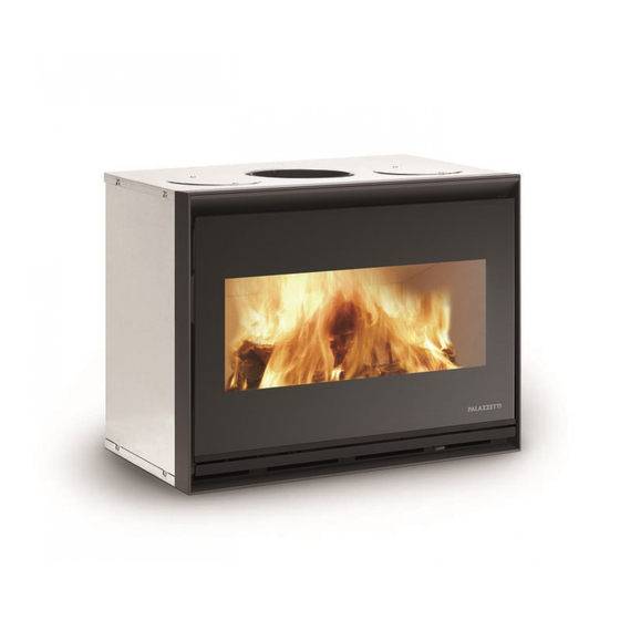
ECOPALEX "Glass"
Il presente manuale è parte integrante del prodotto.
Si raccomanda di leggere attentamente le istruzioni prima
dell'installazione, manutenzione o utilizzo del prodotto.
This manual is an integral part of the product.
Read the instructions carefully before installing, servicing or
operating the product.
Die vorliegende Anleitung ist fester Bestandteil des Produkts.
Vor der Installation, Wartung und Verwendung die Anleitungen
stets aufmerksam durchlesen.
Le présent manuel fait partie intégrante du produit.
Il est conseillé de lire attentivement les consignes
avant l'installation, l'entretien ou l'utilisation du produit.
Este
manual
es
parte
Se recomienda leer detenidamente las instrucciones antes
de la instalación, el mantenimiento y el uso del producto..
integrante
del
producto.
Advertisement
Table of Contents

Related Manuals for Palazzetti Ecopalex Glass


Summary of Contents for Palazzetti Ecopalex Glass
- Page 1 MANUALE DI INSTALLAZIONE USO E MANUTENZIONE INSTALLATION, USER AND MAINTENANCE MANUAL INSTALLATIONS, BEDIENUNGS UND WARTUNGSANLEITUNGEN NOTICE D’INSTALLATION MANUAL DE INSTALACIÓN, USO Y MANTENIMIENTO ECOPALEX “Glass” Il presente manuale è parte integrante del prodotto. Si raccomanda di leggere attentamente le istruzioni prima dell’installazione, manutenzione o utilizzo del prodotto.
- Page 2 Gentile cliente, desideriamo innanzitutto ringraziarLa per la preferenza che ha voluto accordarci acquistando il nostro prodotto e ci congratuliamo con Lei per la scelta. Per consentirLe di utilizzare al meglio la Sua nuova stufa, la invitiamo a seguire attentamente quanto descritto nel presente manuale. Dear Customer, We’d like to thank you for having purchased one of our products and congratulate you on your choice.
- Page 3 INDICE PREMESSA SIMBOLOGIA DESTINAZIONE D’USO SCOPO E CONTENUTO DEL MANUALE CONSERVAZIONE DEL MANUALE AGGIORNAMENTO DEL MANUALE GENERALITÀ PRINCIPALI NORME ANTINFORTUNISTICHE RISPETTATE E DA RISPETTARE GARANZIA LEGALE RESPONSABILITÀ DEL COSTRUTTORE 1.10 CARATTERISTICHE DELL’UTILIZZATORE 1.11 ASSISTENZA TECNICA 1.12 PARTI DI RICAMBIO 1.13 CONSEGNA DEL CAMINETTO AVVERTENZE PER LA SICUREZZA AVVERTENZE PER L’INSTALLATORE...
- Page 4 INDICAZIONE: Indicazioni concernenti il corretto utilizzo da PALAZZETTI carenti o inadeguate a seguito di della stufa e le responsabilità dei preposti. ATTENZIONE: Punto nel quale viene espressa una nota tecnologie su apparecchi di nuova commercializzazione.
- Page 5 PRINCIPALI NORME ANTINFORTUNISTICHE 1.11 ASSISTENZA TECNICA RISPETTATE E DA RISPETTARE Palazzetti è in grado di risolvere qualunque problema Direttiva 2006/95/CE: “Materiale elettrico destinato ad tecnico riguardante l’impiego e la manutenzione nell’intero essere adoperato entro taluni limiti di tensione”. ciclo di vita del prodotto.
- Page 6 AVVERTENZE PER LA SICUREZZA In caso di malfunzionamento della stufa dovuto ad un tiraggio non ottimale della canna fumaria provvedere a fare effettuare una attenta pulizia da AVVERTENZE PER L’INSTALLATORE parte di un tecnico specializzato. dell’apparecchio siano conformi ai regolamenti locali, AVVERTENZE PER IL MANUTENTORE nazionale ed europei.
- Page 7 CARATTERISTICHE E MOVIMENTAZIONE E TRASPORTO DESCRIZIONE Il caminetto viene consegnato in un imballo adeguato ai lunghi trasporti. DESCRIZIONE Consigliamo di disimballare il caminetto solo quando è L’apparecchio è un caminetto da inserimento, costituito giunta sul luogo di installazione. da un monoblocco metallico dalla struttura autoportante. Il caminetto viene consegnato completo di tutte le parti È...
- Page 8 PREPARAZIONE DEL LUOGO DI INSTALLAZIONE SCHEMA DI MONTAGGIO A) Per una corretta installazione la conduttura fumi tra caminetto e canna fumaria va fatta a tenuta stagna sigillando tutti i giunti di unione. C) Le norme UNI prevedono l’installazione di una griglia di recupero di calore il più...
- Page 9 CANNE FUMARIE E COMIGNOLI Il dimensionamento del camino deve essere effettuato in accordo con EN 13384-1. Attenersi alle indicazioni riportate nella scheda tecnica relativamente al valore del tiraggio del camino. La canna fumaria per lo scarico dei fumi deve essere realizzata in osservanza alle norme EN 10683, EN 1856- 1-2, EN 1857, EN 1443, EN 13384-1-3, EN 12391-1, EN15287-1 sia per quanto riguarda le dimensioni che...
- Page 10 OPERAZIONI PRELIMINARI 5.4.1 Interventi di adattamento Prima di tutto è opportuno verificare le dimensioni dello spazio disponibile nel caminetto preesistente e confrontarle con quelle dell’apparecchio e della scheda tecnica. Nel caso si renda necessario un intervento di del caminetto preesistente, si ponga attenzione a non comprometterne la stabilità.
- Page 11 5.4.3 Alloggiamento kit ventilazione 680 m³/h opzionale Per i caminetti esistenti predisporre un vano tecnico sotto la base dell’apparecchio per alloggiare il ventilatore, di 5.4.4 Prese d’aria con kit di ventilazione da 680 m³/h. In aggiunta alla presa dell’aria comburente è necessario eseguire le seguenti prese d’aria per il ventilatore: ventilatore del circuito riscaldamento, posta lateralmente - 5.5 -...
- Page 12 LA CANALIZZAZIONE DELL’ARIA Per il riscaldamento di più locali è possibile dotare l’apparecchio di ventilatore“680” opzionale e realizzare delle condutture metalliche per la distribuzione dell’aria secondo il seguente schema: m per condotto 3+3 m su doppio condotto; 6 m su unico condotto. Predisposizione dell’apparecchio - 5.8 - Distribuzione aria in controcappa:...
- Page 13 Canalizzazione su doppio condotto (-5.11a-) Installare una bocchetta nella stanza stessa del caminetto, la seconda conduttura potrà essere utilizzata per portare l’aria calda in altre stanze della casa. Canalizzazione su unico condotto (-5.11b-) In alternativa collegare entrambe le mandate dell’aria calda con un tubo flessibile fino all’imboccatura degli opportuni canali di distribuzione.
- Page 14 RACCORDO AL CANALE DA FUMO L’apparecchio deve essere collegato alla canna fumaria con tubi e curve in acciaio alluminato o inox. II collegamento può essere effettuato in due modi: A) Collegamento diretto tra caminetto e canna fumaria. Se non è possibile passare con i tubi tra il caminetto e la cappa, è...
- Page 15 INNESTO DEL TUBO TELESCOPICO Caso di installazione su caminetti già esistenti. togliere il sigillante eventualmente traboccato all’interno fumi in ghisa. II raccordo fumi sarà così completato. KIT OPZIONALE CENTRALINA DI REGOLAZIONE VENTILATORI Nella versione con ventilatori assiali l’accensione e la regolazione della velocità possono venire effettuate INTERRUTTORI PER I VENTILATORI Nel caso non venga installata la centralina opzionale di regolazione per i ventilatori, prevedere per l’avvio e...
- Page 16 MESSA IN SERVIZIO ED USO APERTURA DELL’ANTA Per aprire l’anta è necessario utilizzare l’attrezzo fornito in dotazione. Inserire l’attrezzo nell’apposito gancio laterale con cautela per non rischiare di danneggiare il vetro, e ruotare verso l’alto per aprire e verso il basso per chiudere.
- Page 17 6.2.1 Tipo di combustibile La norma di riferimento per il combustibile è la UNI/EN ISO 17225-1 “legna a ciocchi di origine forestale”. La stufa va alimentata preferibilmente con legna di faggio/ betulla ben stagionata oppure con brichette di legno in taglia commerciale da 25 o 33 cm.
- Page 18 entrata dell’aria secondaria. 6.3.1 Regolazione valvola fumi Gli apparecchi sono dotati di una farfalla fumi che consente di regolare il tiraggio in funzione delle dimensioni della canna fumaria. La regolazione della farfalla fumi deve essere eseguita a caminetto freddo. Quando necessario, è possibile aumentare il tiraggio del caminetto a portina chiusa operando come segue: Aprire la portina dell’apparecchio.
- Page 19 MANUTENZIONE E PULIZIA PRECAUZIONI DI SICUREZZA Prima di effettuare qualsiasi operazione di manutenzione o di pulizia adottare le seguenti precauzioni: A) Assicurarsi che tutte le parti del caminetto siano fredde. B) Accertarsi che le braci siano completamente spente. C) Utilizzare i dispositivi di protezione individuale previsti dalla direttiva 89/391/CEE.
- Page 20 MANUTENZIONE DELLA CANNA FUMARIA INFORMAZIONI PER LA DEMOLIZIONE E LO SMALTIMENTO In condizioni di normale funzionamento la pulizia del camino deve essere effettuata ogni 40 q.li di legna L a d e m o l i z i o n e e l o s m a l t i m e n t o bruciata o almeno una volta all’anno salvo diverse dell’apparecchio sono ad esclusivo carico regolamentazioni.
- Page 21 INDEX GENERAL SYMBOLS USE OF THE APPLIANCE PURPOSE AND CONTENTS OF THE MANUAL KEEPING THE MANUAL MANUAL UPDATE GENERAL INFORMATION MAIN ACCIDENT PREVENTION REGULATIONS TO COMPLY WITH LEGAL GUARANTEE MANUFACTURER’S LIABILITY 1.10 USER CHARACTERISTICS 1.11 TECHNICAL ASSISTANCE 1.12 SPARE PARTS 1.13 DELIVERY OF THE APPLIANCE SAFETY PRECUATIONS...
- Page 22 ESPONSIBILITY FOR INSTALLATION It is not PALAZZETTI’s responsibility to carry out the works intake and to check if the installation solutions proposed PURPOSE AND CONTENTS OF THE MANUAL are feasible. All applicable standards and local, national...
- Page 23 1.11 TECHNICAL ASSISTANCE PALAZZETTI is able to solve any technical problem concerning the use and maintenance of the product’s whole life cycle. assistance centre.
- Page 24 SAFETY PRECUATIONS PRECAUTIONS FOR THE MAINTENANCE ENGINEER Comply with the indications given in this manual. INSTRUCTIONS FOR THE INSTALLER Always use individual safety devices and other Make sure that the place of installation of the protection means. and regulations. has been used, it must be completely cold. Comply with the indications given in this manual.
- Page 25 CHARACTERISTICS DESCRIPTION HANDLING AND TRANSPORT The fireplace is delivered with an assembled metal DESCRIPTION structure . an enbloc metal bearing structure. It is suitable for where it will be installed before unpacking it. are distinguished by the revolutionary dual combustion Avoid sudden movements and sharp tugs when lifting system primary combustion gasses optimally.
- Page 26 PREPARING THE PLACE OF INSTALLATION ASSEMBLY DIAGRAM A) For proper installation, the smoke ducting between C) Uni standards require installaiton of a heeat recovery grille as close as possible to the ceiling. aluminium foil G) Minimum distance 1 cm between cladding and The attached product booklet indicates the minimum distances, expressed in cm, which must be respected and objects.
- Page 27 FLUES AND CHIMNEY CAPS The chimney must be dimensioned in compliance with EN 13384-1. Follow the indications in the technical data sheet relating to the chimney draught. The flue pipe for the discharge of smoke must be compliant with standards EN 10683, EN 1856-1-2, EN 1857, EN 1443, EN 13384-1-3, EN 12391-1, EN15287-1 both in terms of size and materials used to construct it.
- Page 28 PRELIMINARY OPERATIONS 5.4.1 Adapting First of all you must check the space available in the appliance and the technical data sheet. If it needs adapting by either cutting or altering the inside walls of its stability. to avoid overheating. 5.4.2 Combustion air intake During operation the takes in a certain amount...
- Page 29 5.4.3 Housing with optional ventilation kit 680 m under the appliance base to house the fan. Its dimensions 5.4.4 Air intakes with optional ventilation kit 680 m³/h. In addition to the combustion air intake, the following air intakes must be provided for the fan: Room air intake to heating circuit fan, located laterally - 5.5 - Depending on the solution adopted, during the dry test...
- Page 30 AIR DUCT with the optional “680” fan and metal pipes for distributing the air as follows: per pipe a double duct; 6 m on just the one duct. Arranging the appliance Remove the top plugs, the front diaphragm and the Secure the upper collars with self-tapping screws - 5.8 - Air distribution in counter hood:...
- Page 31 Double duct piping (Fig. 5.11a) second pipe can be used to carry hot air to the other rooms in the house. Single duct piping (Fig. 5.11b) Alternatively, connect both hot air delivery pipes to a The pipes for distributing air must have an inside cross section of 25 x 15 cm, they must be made in plain galvanised sheet and insulated with a 30 mm thick layer of glass wool to prevent noise and the loss of heat.
- Page 32 SMOKE FITTING - FLUE and curves in aluminate steel or stainless steel. It can be connected in two different ways: If the pipes cannot be made to pass between the fireplace and hood it would be a good idea to facilitate the connection and assembly by making a hole on the B) using the optional telescopic tube kit.
- Page 33 FITTING THE TELESCOPIC PIPE This is the case when you are installing the appliance in on the right and then pulling it out from the left bush. pipe downwards and put it in place. Lastly, remove any excess ealant from inside and put the exaust valve back in place as well as the cast iron smoke diaphragm.
- Page 34 COMMISSIONING AND USING OPENING THE DOOR To open the door, you must use the supplied tool. risking to damage the glass and turn it upwards to open and downwards to close. The door must be opened gradually to allow smoke in the from escaping into the environment.
- Page 35 6.2.1 Type of fuel The normative reference for fuel is ISO 17225-1 “forest logs”. The appliance is to be fed preferably with mature beech or birch wood or with lignite briquettes 25 or 33 cm. Humidity must not exceed 25%. Each type of wood has different characteristics that also contains high quantities of resin substances that quickly It is forbidden to burn: pieces of bark, wood treated with...
- Page 36 the secondary air is let in. 6.3.1 Smoke regulator diaphragm Appliances are equipped with an exhaust valve that The exhaust valve must be adjusted when the When necessary, you may increase draught of the 1) Extracting the smoke diaphragm (-6.3-): Open the appliance door.
- Page 37 MAINTENANCE AND CLEANING SAFETY PRECAUTIONS Before carrying out any maintenance or cleaning, take the following precautions: cold. B) Ensure that embers are completely extinguished. C) Use individual safety gear as set forth by directive 89/391/EEC. D) Always use appropriate tools for maintenance. Maintenance must be carried out by a specialised CLEANING THE GLASS - 7.1 -...
- Page 38 CLEANING THE FLUE INFORMATION FOR DEMOLITION AND DISPOSAL every 40 quintals of wood burnt or at least once a year, unless regulated differently. the sole responsibility of the owner. At any rate, clean at least once a year. When cleaning Dismantling and disposal may be entrusted we suggest removing the smoke diaphragm from the to a third party provided we are talking...
-
Page 39: Table Of Contents
INHALT EINLEITUNG SYMBOLE ANWENDUNGSZWECK ZWECK UND INHALT DES HANDBUCHS AUFBEWAHRUNG DES HANDBUCHS ERWEITERUNG DES HANDBUCHS ALLGEMEINES GRUNDLEGENDE EINGEHALTENE UND EINZUHALTENDE UNFALLVERHÜTUNGSNORMEN GEWÄHRLEISTUNG HAFTBARKEIT DES HERSTELLERS 1.10 EIGENSCHAFTEN DES BENUTZERS 1.11 TECHNISCHER KUNDENDIENST 1.12 ERSATZTEILE 1.13 LIEFERUNG DES KAMINOFENS VORBEUGENDE SICHERHEITSMASSNAHMEN HINWEISE FÜR DEN INSTALLATEUR HINWEISE FÜR DEN BENUTZER HINWEISE FÜR DAS WARTUNGSPERSONAL... -
Page 40: Einleitung
Keinesfalls vorgehen, wenn Sie nicht alle Hinweise des ERSCHLEISS ODER ERLUST Handbuchs verstanden haben; im Zweifelsfall immer den Falls nötig, bei der Fa. PALAZZETTI eine Ersatzkopie Eingriff von Fachpersonal der anfordern. anfordern Die Firma Palazzetti behält sich das Recht vor, pezi kationen und technische bzw. -
Page 41: Grundlegende Eingehaltene Und Einzuhaltende Unfallverhütungsnormen
GRUNDLEGENDE EINGEHALTENE UND 1.11 TECHNISCHER KUNDENDIENST EINZUHALTENDE Die Fa. PALAZZETTI ist in der Lage, jedes technische UNFALLVERHÜTUNGSNORMEN Problem bezüglich der Benutzung oder der Wartung Richtlinie 2006/95/CE: „Elektrisches Material, das während der gesamten Lebensdauer des Produkts zu innerhalb bestimmter Spannungsgrenzen eingesetzt lösen. -
Page 42: Vorbeugende Sicherheitsmassnahmen
VORBEUGENDE eine sorgfältige Reinigung des Schornsteins durch Fachpersonal zu veranlassen. SICHERHEITSMASSNAHMEN HINWEISE FÜR DAS WARTUNGSPERSONAL HINWEISE FÜR DEN INSTALLATEUR Die in diesem Handbuch aufgeführten Vorschriften Sicherstellen, dass die Vorbereitungen für die beachten. Kaminofeninstallation den örtlichen, nationalen und Immer die eigenen Sicherheitsausrüstungen und europäischen Normen entsprechen. -
Page 43: Merkmale Und Gerätebeschreibung
MERKMALE UND HANDLING UND TRANSPORT GERÄTEBESCHREIBUNG Der Kaminofen wird mit montierter Metallstruktur geliefert. Es ist empfehlenswert, den Kaminofen erst am BESCHREIBUNG Installationsort auszupacken. Das Produkt ist ein Einbau-Kaminofen, bestehend aus Das Gerät wird mit allen vorgesehenen Teilen geliefert. einem Metallblock mit selbsttragender Struktur. Er eignet Achtung, das Gerät kippt leicht. -
Page 44: Vorbereitung Des Installationsorts Montageschema
VORBEREITUNG DES INSTALLATIONSORTS MONTAGESCHEMA A) Für eine korrekte installation müssen alle anschlüsse der rauchleitung zwischen kaminofen und rauchfang dicht versiegelt sein. C) Die uni-normen sehen die anbringung eines gitters zur wärmerückgewinnung möglichst nahe der zimmerdecke vor. D) Gegenhaube und tragende, feuerfeste struktur E) Verkleidung aus keramikfaser oder steinwolle mit aluminiumblatt aussen Die holzteile mit feuerfestem material abschirmen... -
Page 45: Rauchfänge Und Schornsteine
RAUCHFÄNGE UND SCHORNSTEINE Der Schornstein muss gemäß EN 13384-1 bemessen werden. Die Angaben zum Zug des Schornsteins im Datenblatt sind zu beachten. Der Rauchfang für die Ableitung der Rauchgase muss unter Beachtung der Normen EN 10683, EN 1856-1-2, EN 1857, EN 1443, EN 13384-1-3, EN 12391-1 , EN15287- 1 angelegt werden, sowohl was seine Größe betrifft als auch das für seinen Bau verwendete Material. -
Page 46: Einleitende Massnahmen
EINLEITENDE MASSNAHMEN 5.4.1 Anpassungsarbeiten Zuerst die im bereits bestehenden Kamin vorhandenen Maße prüfen und mit denen das Gerät auf dem technischen Datenblatt vergleichen. Sollten Anpassungsarbeiten nötig sein, bei denen die Innenwände der Feuerstelle zugeschnitten oder geändert werden, darauf achten, dass die Stabilität des Kamins nicht beeinträchtigt wird. - Page 47 5.4.3 Installation zusätzlicher Belüftungsbausatz 680 m³/h Für bereits bestehende Kamine unter dem Unterbau des Geräts einen Raum für die Installation des Gebläses vorbereiten. Die diesbezüglichen Maße sind in der 5.4.4 Lüftungsklappen mit zusätzlichem Bausatz Belüftung 680 m³/h. Zusätzlich zur Öffnung für die Verbrennungsluftzufuhr müssen folgende Belüftungsöffnungen für den Lüfter angebracht werden: Öffnung Raumluft am Ventilator des Wärmekreislaufs,...
-
Page 48: Die Luftleitung
DIE LUFTLEITUNG Für das Heizen mehrerer Räume kann der Gerät mit einem Ventilator “680” als Option ausgestattet werden, wozu dann Metallleitungen für die Luftverteilung nach folgendem Schema zu verlegen sind: biegsames Aluminiumrohr - max. Länge 2-3 m pro Leitung. glattes Metallrohr oder Schacht - Länge bis zu 3+3 m bei doppelter Leitung;... - Page 49 Schachtverlegung in einer doppelten Leitung (Abb. 5.11a) Einen Stutzen im gleichen Raum des Kaminofens installieren - die zweite Leitung kann für weitere Räume benutzt werden. Schachtverlegung in einer einzigen Leitung (Abb. 5.11b) Andernfalls beide Warmluftströme mit einem biegsamen Rohr bis zum Anschluss an die Verteilerleitungen führen. Die Luftverteilerleitungen müssen innen 25x15 cm messen, aus glattem, verzinktem Stahl gefertigt und zur akustischen bzw.
-
Page 50: Rauchanschluss
RAUCHANSCHLUSS Der Gerät muss mittels Rohren und Krümmungen aus aluminiertem Stahl oder Edelstahl an den Rauchfang angeschlossen werden. Der Anschluss kann auf zwei verschiedene Weisen erfolgen: A) Direkter Anschluss zwischen Kaminofen und Rauchfang. Sollte es nicht möglich sein, die Rohre zwischen Kaminofen und Abzugshaube zu verlegen, ist der Anschluss und die Montage durch eine Öffnung an der Abzugshaube vorzunehmen B) Anschluss mit Teleskoprohr (Option). -
Page 51: Einfügen Des Teleskoprohrs
EINFÜGEN DES TELESKOPROHRS Installation des Gerät in bereits existenten Kaminöfen. Zuerst die Tür öffnen, das gusseiserne Rauchleitblech Rauchklappe zuerst rechts anheben und dann aus der linken Buchse nehmen. Danach das im Teleskoprohr befestigte Rundeisen mit einer Hand nach unten ziehen und in seinen Sitz einfügen. -
Page 52: Inbetriebnahme Und Gebrauch
INBETRIEBNAHME UND GEBRAUCH ÖFFNEN DER TÜR Zum Öffnen der Tür muss das mitgelieferte Werkzeug verwendet werden. Das Werkzeug in den entsprechenden seitlichen Haken einführen, wobei darauf zu achten ist, das Glas nicht zu beschädigen. Zum Öffnen nach oben schieben und zum Schließen nach unten ziehen. Das Öffnen der Tür ist langsam vorzunehmen, damit die Rauchgase vom Zug des Schonsteins abgesaugt werden können und nicht in den Wohnraum gelangen. -
Page 53: Kontrolle Der Verbrennung
6.2.1 Brenstoffe Die Bezugsnorm für den Brennstoff ist die EN ISO 17225- 1 “Wald- und Plantagenholz in Stücken”. Der Kaminofen ist vorzugsweise mit gut getrocknetem Buchen oder Birkenholz oder mit handelsüblichen Holzbriketts von 25 oder 33 cm Länge zu befeuern. Die maximale Feuchtigkeit beträgt 25%. - Page 54 befindlichen Öffnungen in die Feuerstelle. Die Luft entzündet durch ihren Eintritt in die Feuerstelle das noch der primären Verbrennung gebildet hat, und wandelt ) um. Dieser Vorgang ist an den Flammen, die sich um die Öffnungen der Sekundärluft bilden, gut sichtbar. 6.3.1 Einstellung Rauchreglerventil Die Gerät der neuen Serie sind mit einem Rauchreglerventil...
-
Page 55: Instandhaltung Und Reinigung
INSTANDHALTUNG UND REINIGUNG VORBEUGENDE SICHERHEITSMASSNAHMEN Vor dem Durchführen von beliebigen Wartungs- o d e r R e i n i g u n g s m a ß n a h m e n s i n d f o l g e n d e Sicherheitsvorkehrungen zu treffen: A) Sicherstellen, dass alle Kaminofenteile kalt sind. -
Page 56: Reinigung Des Rauchfangs
REINIGUNG DES RAUCHFANGS INFORMATIONEN FÜR DEN ABRISS UND DIE ENTSORGUNG Bei normalem Betrieb muss die Reinigung des Kamins alle 4 t verbranntem Holz oder mindestens einmal jährlich Der Abriss und die Entsorgung des durchgeführt werden, falls keine davon abweichende Kaminofens geht ganz und gar zu Lasten Vorschriften bestehen. - Page 57 INDEX AVERTISSEMENT SYMBOLES UTILISÉS DANS LE MANUEL UTILISATION PRÉVUE BUT ET CONTENU DU MANUEL CONSERVATION DU MANUEL MISE À JOUR DU MANUEL INFORMATIONS GÉNÉRALES PRINCIPALES NORMES DE SÉCURITÉ RESPECTÉES ET À RESPECTER GARANTIE LÉGALE LIMITES DE RESPONSABILITÉ DU FABRICANT 1.10 CARACTÉRISTIQUES DE L’UTILISATEUR 1.11 ASSISTANCE TECHNIQUE...
- Page 58 ENTE DU FOYER Palazzetti se réserve le droit de modifier, à tout En cas de vente du foyer, l’utilisateur est également tenu moment et sans préavis, les spéci cations et les de remettre au nouveau propriétaire le présent manuel.
- Page 59 PRINCIPALES NORMES DE SÉCURITÉ 1.11 ASSISTANCE TECHNIQUE RESPECTÉES ET À RESPECTER PALAZZETTI est en mesure de résoudre tout problème Directive 2006/95/CE: «Matériel électrique destiné technique inhérent à l’utilisation et à l’entretien du produit à être utilisé en respectant les limites de tension pendant toute sa durée de vie.
- Page 60 CONSIGNES DE SÉCURITÉ pas jeter d’eau sur le feu) et appeler les urgences. Ne pas utiliser de la cheminée comme incinérateur de déchets. CONSIGNES POUR L’INSTALLATEUR En cas de dysfonctionnement du poêle dû à un tirage non optimal du carneau, s’adresser à un technicien sont conformes aux règlements locaux, nationaux spécialisé...
- Page 61 CARACTÉRISTIQUES ET DÉPLACEMENT ET TRANSPORT DESCRIPTION La cheminée est livrée avec la structure métallique du foyer montée. DESCRIPTION Il est recommandé de ne déballer la cheminée que L’unité est un foyer constitué d’un monobloc métallique à lorsqu’elle se trouve sur le lieu prévu pour l’installation. structure autoportante.
- Page 62 é e s o n t r é s e r v é e s e x c l u s i v e m e n t aux techniciens spécialisés. Nous conseillons aux utilisateurs de s’adresser au service technique Palazzetti pour demander des techniciens qualifiés. En cas d’interventions de techniciens autres que ceux du service technique Palazzetti, s’assurer qu’ils soient compétents.
- Page 63 CONDUITS DE FUMÉE ET CHEMINÉES DE TOIT Le dimensionnement de la cheminée doit être effectué conformément à la norme EN 13384-1. concernant la valeur du tirage de la cheminée. Le conduit pour l’évacuation des fumées doit être réalisé conformément aux normes EN 10683, EN 1856-1-2, EN 1857, EN 1443, EN 13384-1-3, EN 12391-1, EN15287-1 aussi bien pour ce qui concerne les dimensions que pour les matériaux utilisés pour sa fabrication.
- Page 64 OPÉRATIONS PRÉALABLES 5.4.1 Intervention d’adaptation Il est avant tout nécessaire de contrôler les dimensions de l’espace disponible dans la cheminée existante et de les comparer à celles du foyer le cas où serait nécessaire une intervention d’adaptation veiller à ne pas en compromettre la stabilité. combustible, celles-ci devront être adéquatement isolées du foyer) et se trouver à...
- Page 65 5.4.3 Logement kit ventilation 680 m³/h (optional) Sur les cheminées existantes, prévoir un logement technique sous la base du foyer pour le logement du ventilateur 5.4.4 Prise d’air externe avec kit ventilation 680 m³/h Outre la prise d’air comburant, il est nécessaire d’effectuer les prises d’air suivantes pour le ventilateur: ventilateur du circuit de chauffage, installée sur le côté...
- Page 66 CANALISATION D’AIR Pour pouvoir chauffer plusieurs pièces, il est possible d’installer le foyer avec le ventilateur “680”en option et l’air selon le schéma suivant: par conduite. tuyau métallique lisse ou canalisation - longueur maxi 3+3 m sur double conduit; 6 m sur un seul conduit. Prédisposition de l’appareil - 5.8 - Fixer les colliers supérieurs avec des vis à...
- Page 67 Installer une bouche de sortie dans la pièce où se trouve la cheminée, la deuxième conduite pourra être utilisée pour acheminer l’air chaud dans les autres pièces de l’habitation. Autre solution: relier la sortie de l’air chaud à un tube l’acheminement de l’air.
- Page 68 RACCORD FUMÈES Le foyer doit être raccordé au conduit de cheminée par l’intermédiaire de tuyaux et de coudes en acier aluminé ou inox. Le raccordement peut s’effectuer de deux manières: A) Raccordement direct entre poêle et conduit de cheminée. S’il n’est pas possible de faire passer les tuyaux entre le poêle et la hotte, il est recommandé...
- Page 69 RACCORDEMENT DU TUYAU TÉLESCOPIQUE Cas de l’installation du foyer sur cheminée existante. Il est avant tout nécessaire d’ouvrir complètement la porte, soulevant sur le côté droit et en l’extrayant ensuite de son logement sur le côté gauche. Ensuite tirer vers le bas la tige de jointoiement débordant à...
- Page 70 MISE EN SERVICE ET UTILISATION OUVERTURE DE LA PORTE Pour ouvrir la porte, il faut utiliser l’outil fourni en équipement. Insérer l’outil dans le crochet latéral prévu à cet effet, le faire avec précaution pour ne pas abîmer la vitre, et tourner vers le haut pour ouvrir et vers le bas pour fermer.
- Page 71 6.2.1 Type de combustible La norme de référence pour le combustible est la UNI/EN ISO 17225-1 « bois à buches d’origine forestière ». Le poêle doit être alimenté de préférence avec du bois de hêtre / bouleau bien sec ou avec des briquettes de bois de taille se trouvant dans le commerce de 25 ou 33 cm.
- Page 72 combustion primaire et les transforme en CO formant à hauteur des trous d’arrivée de l’air de combustion secondaire. 6.3.1 Réglage vanne de tirage Les appareils sont équipés d’une valve de gaz de combustion qui se ajuste au tirage en fonction de la taille de la cheminée.
- Page 73 ENTRETIEN ET NETTOYAGE RECOMMANDATIONS DE SÉCURITÉ Avant d’effectuer toute opération de maintenance ou de nettoyage, adopter les précautions suivantes : A) s’assurer que toutes les parties de la cheminée sont bien froides. B) s’assurer que les braises sont complètement éteints. C) utiliser les équipements de protection individuelle prévus par la directive 89/391/CEE.
- Page 74 RAMONAGE DU CONDUIT DE CHEMINÉE INFORMATIONS POUR LA DÉMOLITION ET L’ÉLIMINATION Dans les conditions normales de fonctionnement, le nettoyage de la cheminée doit être effectué tous les La démolition et l’élimination de l’appareil 40 q de bois brûlé ou au moins une fois par an, sauf relève exclusivement de la responsabilité...
- Page 75 ÍNDICE PREÁMBULO SIMBOLOGÍA DESTINO DE USO OBJETO Y CONTENIDO DEL MANUAL CONSERVACIÓN DEL MANUAL ACTUALIZACIÓN DEL MANUAL INFORMACIONES GENERALES PRINCIPALES NORMAS PARA LA PREVENCIÓN DE ACCIDENTES CON QUE SE CUMPLE Y SE DEBE CUMPLIR GARANTÍA LEGAL RESPONSABILIDAD DEL FABRICANTE 1.10 CARACTERÍSTICAS DEL USUARIO 1.11 ASISTENCIA TÉCNICA...
- Page 76 PALAZZETTI, ésta es y sigue siendo a cargo humanos y materiales necesarios para su uso correcto, del instalador, quien debe hacerse cargo de la ejecución seguro y duradero.
- Page 77 PRINCIPALES NORMAS PARA LA 1.11 ASISTENCIA TÉCNICA PREVENCIÓN DE ACCIDENTES CON QUE SE PALAZZETTI es capaz de solucionar cualquier CUMPLE Y SE DEBE CUMPLIR problema técnico sobre el uso y mantenimiento Directiva 2006/95/CE: «Material eléctrico destinado en el entero ciclo de vida del producto.
- Page 78 PRECAUCIONES PARA LA En caso de mal funcionamiento de la estufa, debido a un tiro no óptimo del conducto de salida de humos, SEGURIDAD se debe realizar una atenta limpieza por parte de un técnico especializado. ADVERTENCIAS PARA EL INSTALADOR Comprobar que las predisposiciones para la ADVERTENCIAS PARA EL MANTENEDOR colocación de la chimenea son conformes con los...
- Page 79 CARACTERÍSTICAS Y DESPLAZAMIENTO Y DESCRIPCIÓN TRANSPORTE La chimenea se entrega con la estructura metálica DESCRIPCIÓN montada. El dispositivo está constituido por una chimenea para Se aconseja desembalar la chimenea sólo cuando haya encastrar, que consta de un monobloque metálico con llegado al lugar de destino.
- Page 80 PREPARACIÓN DEL LUGAR DE INSTALACIÓN ESQUEMA DE MONTAJE A) Para la correcta instalación el conducto para la evacuación de los humos entre la chimenea y el cañón de humo debe ser estanco lo que se consigue sellando todos los puntos de unión. C) Las normas uni disponen la instalación de una rejilla de recuperación del calor lo más posible cerca del techo.
- Page 81 CAÑONES Y CHIMENEAS El dimensionamiento de la chimenea debe ser realizado en conformidad con la EN 13384-1. correspondiente al valor del tiro de la chimenea. El cañón para la evacuación de humos debe estar fabricado de conformidad con las normas EN 10683, EN 1856-1-2, EN 1857, EN 1443, EN 13384-1-3 y EN 12391- 1, EN15287-1 tanto en lo referente a las dimensiones como a los materiales utilizados en su fabricación.
- Page 82 OPERACIONES PREVIAS 5.4.1 Operaciones de adaptación Antes de todo es oportuno comprobar las dimensiones del espacio disponible en la chimenea existente y compararlas fuera necesaria una operación de adaptación, cortando o tener cuidado para no afectar a la estabilidad de la chimenea. La viga de madera eventual, o cualquier terminación en material combustible, debe aislarse oportunamente mantener respecto al equipo una distancia de 1 metro...
- Page 83 5.4.3 Alojamiento con kit de ventilación a elegir de 680m /h (optional) Para las chimeneas existentes, disponer un compartimento técnico debajo de la base del equipo para alojar el ventilador, de tamaño al menos igual a lo indicado en 5.4.4 Tomas de aire con kit de ventilación a elegir de 680m Como adición a la toma de aire comburente, es necesario...
- Page 84 LA CANALIZACIÓN DEL AIRE Para la calefacción de varias habitaciones es posible dotar el dispositivo con un ventilador “680”opcional y realizar unos conductos metálicos para el reparto del aire según el esquema siguiente: conducto. largo para doble conducto; 6 m para conducto único Preparación del equipo - 5.8 - Fije los collares superiores con tornillos autorroscados...
- Page 85 Canalización para doble conducto (Fig. 5.11a) Instalar una boquilla en el mismo cuarto de la chimenea, el segundo conducto se podrá utilizar para llevar el aire caliente a los otros cuartos de la vivienda. Canalización para conducto único (Fig. 5.11b) E n a l t e r n a t i v a , c o n e c t a r l a a l i m e n t a c i ó...
- Page 86 EMPALME DE HUMOS El dispositivo se debe empalmar con el cañón de humo por medio de tubos y codos de acero aluminoso o inoxidable. El empalme se puede realizar de dos formas: A) Empalme directo de la chimenea con el cañón de humo.
- Page 87 INSERCIÓN DEL TUBO TELESCÓPICO Estas instrucciones sirven en caso de que se incorpore el dispositivo a chimeneas existentes. primero por el lado derecho y luego sacarla del casquillo de la izquierda. Después, tirar hacia abajo con una mano su alojamiento. Finalmente, quitar la masilla que en la eventualidad hubiera desbordado en el interior y volver humos de hierro fundido.
- Page 88 PUESTA EN MARCHA Y USO APERTURA DE LA PUERTA Para abrir la puerta es necesario utilizar la herramienta que se suministra. Introduzca la herramienta en el gancho lateral correspondiente con cuidado para no correr el riesgo de dañar el vidrio, y gire hacia arriba para abrir y hacia abajo para cerrar.
- Page 89 6.1.2 Tipo de combustible La norma de referencia para el combustible es la UNI / EN ISO 17225-1 “leña en trozos de origen forestal”. La estufa debe ser alimentada con leña, preferiblemente de haya / abedul bien seca o con briquetas de madera de tamaño comercial de 25 o 33 cm.
- Page 90 durante la combustión primaria, transformándolos en gas ). El efecto se ve perfectamente con la formación de un tapete de llamas en correspondencia con 6.2.1 Válvula de regulación de los humos Los dispositivos están equipados con una válvula de humos de combustión que ajusta el sorteo dependiendo del tamaño de la chimenea.
- Page 91 MANTENIMIENTO Y LIMPIEZA PRECAUCIONES DE SEGURIDAD Antes de efectuar cualquier tipo de operación de mantenimiento o de limpieza, adopte las siguientes precauciones: A) Comprobar que todas las piezas de la chimenea estén frías. B) C o m p r o b a r q u e l a c e n i z a e s t é t o t a l m e n t e apagada.
- Page 92 LIMPIEZA DEL CAÑÓN DE HUMO INFORMACIONES PARA EL DESGUACE Y LA ELIMINACIÓN En condiciones de funcionamiento normal, la limpieza de la chimenea debe ser realizada cada 4 toneladas E l d e s g u a c e y l a e l i m i n a c i ó n d e l de leña quemada o al menos una vez al año, excepto equipo corren a cargo y están bajo la reglamentaciones diferentes.
- Page 96 Palazzetti accepts no liability for any mistakes in this handbook and is free to modify the features of its products without prior notice.
Need help?
Do you have a question about the Ecopalex Glass and is the answer not in the manual?
Questions and answers