Table of Contents
Advertisement
Quick Links
No. CP-SP-1439E
Dynamic Self-Checking
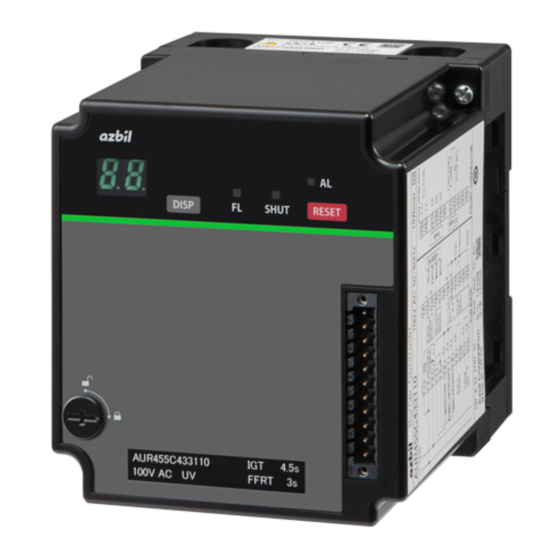
Burner Controller
Model AUR455
User's Manual
Thank you for purchasing an Azbil
Corporation product.
This manual contains information for
ensuring the correct use of this product.
It also provides necessary information
for installation, maintenance, and
troubleshooting.
This manual should be read by those
who design and maintain equipment
that uses this product. Be sure to keep
this manual nearby for handy reference.
Advertisement
Table of Contents

Related Manuals for Azbil AUR455


Summary of Contents for Azbil AUR455
- Page 1 No. CP-SP-1439E Dynamic Self-Checking Burner Controller Model AUR455 User’s Manual Thank you for purchasing an Azbil Corporation product. This manual contains information for ensuring the correct use of this product. It also provides necessary information for installation, maintenance, and troubleshooting.
- Page 2 NOTICE Please make sure that this manual is available to the user of the product. Unauthorized duplication of this user’s manual in part or in whole is forbidden. The information and specifications in this manual are subject to change without notice. Considerable effort has been made to ensure that this manual is complete and accurate, but if you should find an omission or error, please contact us.
-
Page 3: Conventions Used In This Manual
Conventions Used in This Manual „ The safety precautions explained below aim to prevent injury to you and others, and to prevent property damage. Warnings are indicated when mishandling this product may WARNING result in death or serious injury. Cautions are indicated when mishandling this product may CAUTION result in minor injury or property damage only. -
Page 4: Safety Precautions
Safety Precautions WARNING This device is equipped with functions that are extremely important for the safe operation of combustion equipment. Be sure to follow the instructions stated in this user’s manual. This device does not have a prepurge function. Use this device as part of a system whose design gives careful consideration to the prepurge timer and ignition sequence timing, following established safety guidelines. - Page 5 WARNING Before doing the pilot turn-down test, always make sure that all manual fuel valves are closed. If the pilot turn-down test must be repeated, stop the combustion equipment completely each time and discharge all of the unburned gas and oil from the fuel chamber and flue. Failure to discharge unburned gas may result in an explosion hazard.
- Page 6 CAUTION Do not connect a load that exceeds the rating stated in the specifications to the control load terminals (6, 7, 8), and do not short-circuit the load. Doing so will burn out the internal fuse, making this device unusable. The protection rating of this device is equivalent to IP10 or IP40.
-
Page 7: The Role Of This Manual
The Role of This Manual There are three different manuals related to model AUR455. Read them as necessary for your specific requirements. If you do not have a manual you require, please contact us or one of our dealers. Dynamic Self-Checking Burner Controller Model AUR455 User’s Manual Document No. -
Page 8: Table Of Contents
Host communication setting using the Smart Loader Package (model SLP-A55) „ Chapter 4. Explanation of Operation „ Instrumentation example of model AUR455 for an interrupted pilot „ Notes about the instrumentation and circuit configuration for an interrupted pilot „ Internal block diagram (interrupted pilot) „... - Page 9 Chapter 5. Trial Operation and Adjustment Preliminary inspection „ Inspection procedure „ Chapter 6. Maintenance and Inspection „ General maintenance and inspection „ Maintenance and inspection cycle „ Alarm codes and details „ What to do if E951 occurs „ Failure inspection flowchart Chapter 7.
-
Page 11: Overview
AUD300C advanced ultraviolet flame detector, the AUD500C explosion-proof advanced ultraviolet flame detector, or a flame rod. The AUR455 drives the shutter that is built into the AUD300C/500C to continuously check both its own flame detection circuit and the ultraviolet detector in order to provide flame detection for continuous burner operation. -
Page 12: Cautions For Combustion Equipment Design
Chapter 1. Overview „ Cautions for combustion equipment design Facilities that use flame safeguard system must be designed in compliance with relevant laws, standards, safety guidelines, and the like. If the system is designed to foreign specifications, please observe the local laws and standards. -
Page 13: Model No
Power Pilot Other Description Note model detector trial trial failure sequence response AUR455 Flame rod CE certification CE certification 4.5±0.5 s 9.0±1.0 s 7.0±1.0 s 4.5±0.5 s JIS response time 2 s max. AUR455C only 4 s max. 100 V AC... -
Page 14: Related Devices
With tropicalization and inspection certificate With traceability certificate and tropicalization Optional parts (sold separately) Model No. Name BC-R05A100 Dedicated sub-base (a requirement for the AUR455) 81447514-001 Connector for front wiring Weidmüller model number BL3.5/11F Compatible wire: 0.2–1.5 mm (28–14 AWG) -
Page 15: Installation, Wiring
Chapter 2. Installation, Wiring WARNING Do not reset this device from a remote location. Because it is difficult to make a safety check when far from the equipment, there is an increased risk of explosion. This device is equipped with functions that are extremely important for the safe operation of combustion equipment. - Page 16 AUR455 devices. Do not share the output common (terminals 4 & 5) and the input common (terminals 19 & 20) with other AUR455 devices. Do not provide instrumentation to stop the power to the device as soon as the alarm operates.
-
Page 17: Installation Method
Chapter 2. Installation, Wiring „ Installation method WARNING Before mounting, removing, or wiring, be sure to turn off the power to this device and all connected devices. Failure to do so may result in electric shock. CAUTION Installation, wiring, maintenance, inspection, and adjustment must be carried out by a professional with technical training in combustion equipment and flame safeguard system. -
Page 18: Cautions Regarding Installation
Chapter 2. Installation, Wiring „ Cautions regarding installation • Leave space 50 mm above and below, 50 mm on the left and right, and 80 mm in the front as space for removal, wiring, and maintenance. Also, do not install this device close to electrical power devices or other sources of heat. -
Page 19: Mounting On A Din Rail
Chapter 2. Installation, Wiring „ Mounting on a DIN Rail (1) Pull down the sub-base’s DIN rail clamps. (2) Attach the sub-base to the DIN rail, making sure that the sub-base is not upside-down. (3) Push up the DIN rail clamp to fasten the sub-base to the DIN rail. Attach sub-base to DIN rail Pull down the DIN rail clamps Push the DIN rail clamps... -
Page 20: Mounting/Removing The Unit And The Sub-Base
Chapter 2. Installation, Wiring CAUTION Turn the power off before mounting the device on the sub-base. Otherwise, device failure may result. „ Mounting/removing the unit and the sub-base Mounting (1) Align the indentation in the center of the top of the device with the projection on the sub-base. -
Page 21: Terminal No
Chapter 2. Installation, Wiring „ Terminal No. Sub-base terminals Code Function Code Function Load power Not used AC-H Power (H) Flame detector (F) AC-G Power (G) Flame detector (G) Shutter output 1 COM-G1 Output common 1 (AUR455C only) Shutter output 2 COM-G2 Output common 2 (AUR455C only) - Page 22 Chapter 2. Installation, Wiring Connector for front wiring (model 81447514-001) terminal layout Mounting screw Wiring Screws for wiring Mounting screw Connector for front wiring (for right side wiring) (model 81447514-002) terminal layout Mounting screw Wiring Screws for wiring Mounting screw...
-
Page 23: Example Of Wiring With External Devices
• After mounting the connector for front wiring, secure it in place with the mounting screw on the side of the connector. • Use the contact reset input (terminal 24) for one AUR455 only. Do not use the terminal for contact reset input to other AUR455 devices. - Page 24 • After mounting the connector for front wiring, secure it in place with the mounting screw on the side of the connector. • Use the contact reset input (terminal 24) for one AUR455 only. Do not use the terminal for contact reset input to other AUR455 devices.
-
Page 25: Connection With Model Aud300C/500C
Chapter 2. Installation, Wiring „ Connection with model AUD300C/500C Connect to the AUD300C or AUD500C as shown. AUD300C/500C AUR455 16 17 Blue Yellow White White Handling Precautions • AUD300C and 500C signal wires (blue and yellow) have polarity. Connect the blue wire to terminal 14 (F), and the yellow wire to terminal 15 (G). -
Page 26: Connections To Solenoid Valve
Connect the load (ignition transformer, solenoid valve, etc.) directly to the output terminals of this device. If it is not directly connected, combustion safety cannot be ensured. Operation in case of a ground fault AUR455 High-voltage side (L1) Low-voltage side... -
Page 27: Operation
Chapter 3. Operation „ Part names Shutter LED (green) 7-segment LED (green) The LED is ON when the flame detection circuit is being checked. When normal: sequence code / flame voltage / event code Main unit mounting screw When an error occurs: alarm code / Alarm LED (red) flame voltage DISP switch... - Page 28 Chapter 3. Operation z When an error occurs The 7-segment display alternately displays an alarm code and the code for the sequence step where the lockout occurred. Every time the DISP switch is pressed, the display changes between the flame voltage and alternate display of the alarm code and sequence code when lockout occurred.
- Page 29 Chapter 3. Operation Press the RESET switch for 3 s or longer or short the contact reset input for 3 s or longer to clear all active events at the same time. However, note that the RESET switch and contact reset input cannot be used to clear events during lockout. Display Event name Operation...
-
Page 30: Turn-Down Test And Communication Setting Modes
Chapter 3. Operation „ Turn-down test and communication setting modes WARNING Loads operate for the blower, ignition transformer, valves, etc., in turn-down test and communication setting modes. The operator should be a specialist with comprehensive knowledge of the combustion equipment and the functions of this device. Otherwise there is a risk of a major accident. - Page 31 Chapter 3. Operation z When a selection from is made • Communication address setting ( Use the DISP switch to select on the 7-segment display. 1. Press the RESET switch. The 7-segment display shows /_ _. _ _ is the address value. (Default setting: 1) 2.
- Page 32 Chapter 3. Operation • Initialization of settings ( Use the DISP switch to select on the 7-segment display. 1. Press the RESET switch. The 7-segment display shows 2. When the DISP switch is pressed in this situation, the display toggles between (no) and (yes).
- Page 33 Chapter 3. Operation „ Host communication setting using the Smart Loader Package (model SLP-A55) Handling Precautions • Until configuration is complete, do not turn off the power or remove the loader cable. If the power is turned off during configuration, there may be an error.
-
Page 35: Explanation Of Operation
„ Notes about the instrumentation and circuit configuration for an interrupted pilot In instrumentation and circuit configuration of the AUR455 for an interrupted pilot, note the following: • For safety control and operation circuitry, implement inherent safety design measures based on risk assessment. -
Page 36: Internal Block Diagram (Interrupted Pilot)
Chapter 4. Explanation of Operation „ Internal block diagram (interrupted pilot) An example of wiring for external devices and an internal block diagram are shown below. L2(N) Emergency stop circuit Blower on-off circuit / prepurge circuit Gas pressure Gas pressure Overheating Seismic Air pressure... - Page 37 Chapter 4. Explanation of Operation L2(N) Emergency stop circuit Blower on-o circuit / prepurge circuit Gas pressure Gas pressure Overheating Seismic Air pressure low limit interlock high limit interlock limit limit low limit interlock Power circuit Diagnostic circuit Flame rod 10 A Flame detection...
-
Page 38: Sequence Chart
ON in the case of a direct ignition model, OFF in the case of an interrupted pilot model. This is because the AUR455 has one output with different operation depending on the type of model, while the AUR450 has two outputs for the pilot valve, one for the intermittent and one for the interrupted type. - Page 39 Chapter 4. Explanation of Operation Operation during start check error (false flame) If a false flame is detected during the start check, and the error is not cleared after 5 seconds, lockout occurs. While a false flame is detected, the flame monitor output is ON.
- Page 40 ON in the case of a direct ignition model, OFF in the case of an interrupted pilot model. This is because the AUR455 has one output with different operation depending on the type of model, while the AUR450 has two outputs for the pilot valve, one for the intermittent and one for the interrupted type.
- Page 41 ON in the case of a direct ignition model, OFF in the case of an interrupted pilot model. This is because the AUR455 has one output with different operation depending on the type of model, while the AUR450 has two outputs for the pilot valve, one for the intermittent and one for the interrupted type.
-
Page 42: Instrumentation Example Of Model Aur455 For An Intermittent Pilot
Chapter 4. Explanation of Operation „ Instrumentation example of model AUR455 for an intermittent pilot Overheating limit Limit/interlock Seismic limit Controller BC for pilot burner (AUR455) Seismic part BC for main burner (AUR455) Air pressure Flame detector for main burner... -
Page 43: Internal Block Diagram (Intermittent Pilot)
Configure the circuit using the main burner ignition permission output (pilot flame ignition signal) as the condition for starting the main burner controller or as the condition for interlock. Provide a separate external reset input for each individual AUR455. Do not share the external reset input terminal with other AUR455 devices. - Page 44 Configure the circuit using the main burner ignition permission output (pilot flame ignition signal) as the condition for starting the main burner controller or as the condition for interlock. Provide a separate external reset input for each individual AUR455. Do not share the external reset input terminal with other AUR455 devices.
-
Page 45: Wiring For Replacement Of Model Aur450
Chapter 4. Explanation of Operation „ Wiring for replacement of model AUR450 Wiring for model AUR450 L2(N) Emergency stop circuit Blower on-off circuit / prepurge circuit Gas pressure Gas pressure Overheating Seismic Air pressure low limit interlock high limit interlock limit limit low limit interlock... - Page 46 The interlock that was connected in series with the load to terminal 18 of the AUR450 can be connected to terminal 1 of the AUR455. If this interlock in series with the load opens during combustion, the fuel valve will shut off and the flame will be extinguished.
-
Page 47: Alarms And Combustion Sequence
Chapter 4. Explanation of Operation „ Alarms and combustion sequence Interlock False Ignition Flame UV alarm error flame failure failure Name Code Stop Start check Ignition trial Pilot only / Hi solenoid valve ignition standby Main trial / Hi... -
Page 49: Chapter 5. Trial Operation And Adjustment
Chapter 5. Trial Operation and Adjustment WARNING The ignition time for the pilot and main burners should not exceed the time defined by the burner or device manufacturer. If it does, fuel will accumulate in the combustion chamber and form an explosive mixture, resulting in a very dangerous situation in which an explosion could occur. - Page 50 Chapter 5. Trial Operation and Adjustment Ignition spark response WARNING Make sure that the AUD flame detector does not detect UV rays from a source other than the burner. Before doing the spark response test, make sure that all manual fuel valves are closed. (1) Close the manual valves in the piping for the pilot and main burners.
- Page 51 The voltage can be checked on the 7-segment display or by connecting a flame meter to terminals 25 & 26 on the front connector. It is necessary to obtain a monitor/communication connector (81447514-001) to connect the FSP136A100 and the AUR455. Flame voltage display...
- Page 52 Chapter 5. Trial Operation and Adjustment Pilot turn-down test WARNING Carry out the pilot turn-down test carefully. Before doing the pilot turn-down test, always make sure that all manual fuel valves are closed. If the pilot turn-down test must be repeated, stop the combustion equipment completely each time and discharge all of the unburned gas and oil from the fuel chamber and flue.
- Page 53 Chapter 5. Trial Operation and Adjustment Note • When turn-down test or communication setting mode is used, pilot burner combustion continues and there is no limitation on the pilot burner ignition time. Therefore, the smallest effective pilot flame can be easily determined. (5) Turn off the power switch, return the main valve to its normal state (open the manual cock) and then turn on the power switch again.
-
Page 55: Chapter 6. Maintenance And Inspection
Chapter 6. Maintenance and Inspection WARNING Before mounting, removing, or wiring, be sure to turn off the power to this device and all connected devices. Failure to do so may result in electric shock. Do not touch terminal 14 (F) after turning the power off. An electric charge may remain on terminal 14 (F) and cause an electric shock. -
Page 56: Alarm Codes And Details
Chapter 6. Maintenance and Inspection „ Alarm codes and details When a lockout occurs, the alarm code and the code for the sequence step where the lockout occurred are displayed alternately. If the sequence step cannot be identified, the sequence code may be displayed as “--” (stopped). For the relationship between the combustion sequence and alarm codes, see „Alarms and combustion sequence (Page 37). - Page 57 Chapter 6. Maintenance and Inspection Alarm Sub- Description Status Cancellation method code code Internal error EEPROM write Error while writing to the EEPROM Reset Internal error process data value Internal memory error Reset System error (1) CPU communication error Reset Internal error (input-circuit) Detection of part failure (voltage applied to Reset...
-
Page 58: What To Do If E951 Occurs
Chapter 6. Maintenance and Inspection „ What to do if E951 occurs E951 occurs when the data read from the burner controller’s EEPROM is abnormal. In order to write data correctly into the EEPROM, the following operations are required before and after resetting E951. (1) If E951 occurs, do not reset the error immediately. -
Page 59: Failure Inspection Flowchart
Chapter 6. Maintenance and Inspection „ Failure inspection flowchart WARNING Before mounting, removing, or wiring, be sure to turn off the power to this device and all connected devices. Failure to do so may result in electric shock. If there is a problem with the equipment, follow the inspection procedure below. Turn the start input OFF and reset by pressing the RESET switch... -
Page 61: Chapter 7. Specification
Chapter 7. Specification Item Description Application Gas- or oil-burning combustion equipment Compatible flame detector Model AUD300C/500C UV flame detector or flame rod Sequence Sequence timing Ignition trial: Selectable by model No. Pilot only (Hi solenoid valve ignition standby)* : 7.0±1.0 s Main trial (Hi solenoid valve ignition)* Selectable by model No. - Page 62 Chapter 7. Specification Item Description General Protective structure IP40: if sideboards (81447515-001) are attached to the sub-base (model BC-R05) specifications IP10: sub-base (model BC-R05) only Overvoltage category Pollution degree Automatic action Type 2.A.V (IEC 60730-1 / JIS C 09730 001) Software Class C Case color...
-
Page 63: X84; External Dimensions
Chapter 7. Specification „ External dimensions Main unit Unit: mm Sub-base (sold separately) Main unit mounting screw Sub-base (sold separately) Connector for front wiring Main unit mounting screw DIN rail clamp Model No. of connector for front wiring 81447514-001 10.6 81447514-002 14.6... - Page 64 Chapter 7. Specification Sub-base model BC-R05A100 (sold separately) Unit: mm Knockout hole Knockout hole M3.5 (terminal screw) φ12 knockout hole φ12 knockout hole Sub-base Sub-base mounting hole mounting hole 62.5 DIN rail clamp Sideboard model 81447515-001 (sold separately) 30.7 Sub-base Sub-base...
- Page 65 Revision History of CP-SP-1439E Date Rev. (New) Page No. Description Feb. 2021...
- Page 66 Warranty period and warranty scope 1.1 Warranty period Azbil Corporation’s products shall be warranted for one (1) year from the date of your purchase of the said products or the delivery of the said products to a place designated by you.
- Page 67 Although acceleration of the above situation varies depending on the conditions or environment of use of the products, you are required not to use any Azbil Corporation’s products for a period exceeding ten (10) years unless otherwise stated in specifications or instruction manuals.
- Page 68 Specifications are subject to change without notice. (11) 1-12-2 Kawana, Fujisawa Kanagawa 251-8522 Japan https://www.azbil.com 1st edition: Feb. 2021 (F)
Need help?
Do you have a question about the AUR455 and is the answer not in the manual?
Questions and answers