Table of Contents
Advertisement
Quick Links
(Not for use in Japan)
No. CP-SP-1461E
™
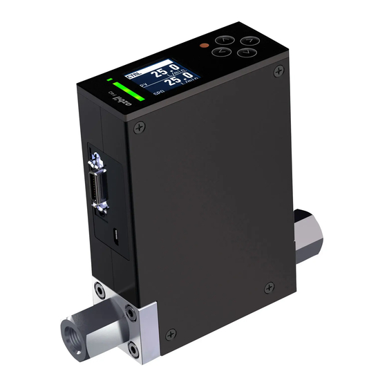
Digital Mass Flow Controller
Model F4Q
User's Manual
Thank you for purchasing this product.
This manual contains information for
ensuring the safe and correct use of
the product.
Those designing or maintaining
equipment that uses this product
should first read and understand
this manual. This manual contains
information not only for installation,
but also for maintenance,
troubleshooting, etc. Be sure to keep it
nearby for handy reference.
Advertisement
Table of Contents

Related Manuals for Azbil F4Q


Summary of Contents for Azbil F4Q
- Page 1 (Not for use in Japan) No. CP-SP-1461E ™ Digital Mass Flow Controller Model F4Q User’s Manual Thank you for purchasing this product. This manual contains information for ensuring the safe and correct use of the product. Those designing or maintaining...
- Page 2 Considerable effort has been made to ensure that this manual is complete and accurate, but if you should find an omission or error, please contact us. In no event is Azbil Corporation liable to anyone for any indirect, special, or consequential damages as a result of using this product.
- Page 3 Conventions Used in This Manual „ The safety precautions explained below aim to prevent injury to you and others, and to prevent property damage. Warnings are indicated when mishandling this product may WARNING result in death or serious injury. Cautions are indicated when mishandling this product may CAUTION result in minor injury or property damage only.
- Page 4 Safety Precautions WARNING Never allow gases that are within explosive limits to pass through this device. Doing so might result in an explosion. If you allowed a gas that contains oil to pass through this device, do not allow oxygen to enter this device afterward.
- Page 5 Excessive force may damage the product. Do not disassemble this device. There is a danger of device failure. Azbil products are industrial products subject to the WEEE Directive. Do not dispose of electrical and electronic equipment in the same way as household waste.
- Page 6 CAUTION Do not turn off the power when settings are being written via RS-485 communication, when settings are being changed using the PC loader, or during zero point adjustment. There is a danger of device failure. Do not apply voltage to the instantaneous flow rate setting input terminal while the power is off.
- Page 7 The Role of This Manual There are four different manuals related to model F4Q. Read them as necessary for your specific requirements. If a manual you require is not available, contact the azbil Group or one of its dealers. Digital Mass Flow Controller Model F4Q User’s Manual Document No.
-
Page 8: Table Of Contents
Contents Conventions Used in This Manual Safety Precautions The Role of This Manual Chapter 1. Overview Overview „ Features „ Model selection guide „ „ Functions Chapter 2. Names and Functions of Parts „ Top panel „ Main unit (model F4Q9200/9500/0002/0005/0020/0050) Chapter 3. - Page 9 5 - 2 Function Details „ Display-related „ Analog input/output 5-14 „ Digital input/output 5-16 „ Flow rate control 5-20 „ Measurement conditions, flow rate correction 5-26 „ Flow rate totalization 5-31 Fail-safe function 5-34 „ 5 - 3 Displaying Device Information 5-36 Procedure for displaying device information 5-36...
-
Page 11: Features
Chapter 1. Overview „ Overview This device is a high-performance digital mass flow controller with advanced functions for the general industrial market. It features high accuracy, high-speed response, and a wide control range. Mass flow controller Cable with dedicated connector Controller (optional) (model C25/26, etc.) - Page 12 Chapter 1. Overview • Ease of use The product runs on 24 V DC from a single general-purpose power supply. In addition, the power supply circuit and I/O circuit inside the device are isolated. When multiple F4Qs are driven through analog input/output using a programmable logic controller (PLC) or the like, even if the analog module channels on the PLC side are not isolated, a common power supply can be used to power the units.
-
Page 13: Model Selection Guide
Chapter 1. Overview „ Model selection guide Face-to-face: 90 mm (with fluoroelastomer gaskets) 10 11 12 13 14 15 16 17 Description 2 to 200 mL/min (normal)* 5 to 500 mL/min (normal)* 0.02 to 2 L/min (normal)* 0.05 to 5 L/min (normal)* 0.2 to 20 L/min (normal)* 0.5 to 50 L/min (normal)* Integrated-display model... - Page 14 Chapter 1. Overview Face-to-face: 90 mm (with EPDM gaskets) 10 11 12 13 14 15 16 17 Description 2 to 200 mL/min (normal)* 5 to 500 mL/min (normal)* 0.02 to 2 L/min (normal)* 0.05 to 5 L/min (normal)* 0.2 to 20 L/min (normal)* 0.5 to 50 L/min (normal)* Integrated-display model Separate-display model...
-
Page 15: Functions
Chapter 1. Overview „ Functions The configuration of the main screen and operations often used during steady operation, such as flow rate setting and switching of the valve operation mode, are described in Chapter 4. Basic Operations. Other functions and screen display switching are described in Chapter 5. - Page 16 Chapter 1. Overview Function Overview Refer to Flow rate control Flow rate setting The flow rate can be changed using the operation Chapter 4. Basic keys, digital input, analog input, or communication. Operations Direct setup function When the flow rate setting is changed using the keys, the entered value is applied immediately as the control SP.
- Page 17 Data can be exchanged with host devices – function (master stations) such as a PC or a PLC via RS-485 communication. Digital Mass Flow Controller Model F4Q User’s Manual for RS-485 Communication Functions (CP-SP- 1458E) Loader Device setup and A simplified engineering software tool (loader) that Chapter 6.
-
Page 19: Names And Functions Of Parts
Chapter 2. Names and Functions of Parts „ Top panel Status indicator Communication indicator Display Valve control key Arrow keys Part name Application Status indicator An LED to indicate abnormalities or valve control status Communication An LED to indicate the communication status of the device indicator Display Used to monitor controlled values or to specify settings. -
Page 20: Main Unit (Model F4Q9200/9500/0002/0005/0020/0050)
Chapter 2. Names and Functions of Parts „ Main unit (model F4Q9200/9500/0002/0005/0020/0050) Integrated model Arrow keys Top panel Display Connector for external connection Micro USB terminal for loader Inlet pipe Outlet pipe connection port connection port Separate model Connector for separate display unit Connector for external connection... -
Page 21: Mounting And Wiring
Chapter 3. Mounting and Wiring WARNING Never allow gases that are within explosive limits to pass through this device. Doing so might result in an explosion. Do not use this device in explosive atmospheres or near flammable fluids or steam. CAUTION Do not allow lint, metal shavings, water, etc., to enter the case of this device. -
Page 22: Mounting
Chapter 3. Mounting and Wiring „ Mounting CAUTION When installing, securely attach the device using the mounting holes on its base to prevent vibration. Otherwise, a malfunction or failure may result. Mount this device in a location that satisfies the operating conditions given in the specifications. - Page 23 Chapter 3. Mounting and Wiring Installing fittings for UNF connections When attaching the fitting (on a UNF connection), hold the lower part of the main unit in a vise gripped between rags to protect the finished surfaces, and turn the fitting to tighten.
- Page 24 Chapter 3. Mounting and Wiring Installing the separate display unit When a separate-display model is used • Advance preparation Make mounting holes in the panel according to the panel cutout dimensions. Independent mounting Gang mounting Recommended panel cutout dimensions 30 min. (93 x N-4) ±0.2 ±0.2...
-
Page 25: Piping
Chapter 3. Mounting and Wiring „ Piping CAUTION Prevent foreign matter from entering the flow path of this device. If rust, water droplets, oil mist, or dust from the pipes enters the device, a measurement or control error may occur, or the device may be damaged. -
Page 26: Wiring
Chapter 3. Mounting and Wiring „ Wiring CAUTION Make sure that devices or equipment connected to this device have reinforced insulation or double insulation suitable for the maximum voltages of this device’s power supply and input/ output components. Otherwise, there is a danger of electric shock. If there is a risk of a power surge caused by lightning, use a surge absorber (surge protector). - Page 27 Straight long DF02D020B22 z Connector signal table Signal name Description Notes RS-485 comm., DA Digital Mass Flow Controller Model F4Q User’s Manual RS-485 comm., DB for RS-485 Communication Functions (CP-SP-1458E) (for the connection procedure) S.GND RS-485 comm. (−) Analog input (+) Flow rate set point (SP) input 0–5 V, 1–5 V, or 4–20 mA input...
- Page 28 • Connect two wires in parallel to the power supply in order to reduce voltage drop caused by wiring resistance. z RS-485 communication S.GND Note • Digital Mass Flow Controller Model F4Q User’s Manual for RS-485 Communication Functions (CP-SP-1458E) (for the connection method of RS-485 communication) z Digital output Load Load Load D.GND...
- Page 29 Chapter 3. Mounting and Wiring z Analog input/output Input: 0–5 V, 1–5 V, or 4–20 mA Output: 0–5 V, 1–5 V, or 4–20 mA A.GND Wiring example External circuit Internal circuit S.GND Input: 0–5 V, 1–5 V, or 4–20 mA Output: 0–5 V, 1–5 V, or 4–20 mA I/O circuit A.GND...
-
Page 31: Basic Operations
Chapter 4. Basic Operations 4 - 1 Main Screen Display CAUTION Do not operate the keys with a sharp-tipped object such as mechanical pencil or screwdriver. Device failure may result. The screen that appears on the display after power-on is called the main screen. The main screen consists of the top section, the bottom section, and the status bar. -
Page 32: Flow Rate Setting
„ Bottom section of the main screen: Multi-information display The SP is displayed in the bottom section of the main screen that appears at power- You can display the following multiple types of information by pressing the [∧] or [∨] key. SP, totalized flow volume, gas type, user-specified tag, valve opening, full scale flow rate ∧... - Page 33 Totalized flow volume The display unit for the totalized flow volume can be selected from [mL], [L], and ] with C43 (totalized flow rate unit (display)). Note • z Function code setup (p. 5-1) (for how to set the function codes) Up to 10 digits can be displayed. If mL is selected as the unit, the display unit is automatically switched to L if the value has more than 10 digits.
- Page 34 User-specified tag Any character string consisting of up to seven characters can be displayed. Note • The user-specified tag can be set using the loader. z User tag specification (p. 6-5) (for details) Valve opening The degree of valve opening (MV) is displayed by 0 to 100 %. Full scale flow rate The full scale flow rate (the maximum control range for the selected gas type) is displayed.
-
Page 35: Status Bar
„ Status bar Various kinds of information (valve operation mode, event status, and key lock status) can be seen on the status bar. Status bar Valve operation mode Control Fully open Fully closed Maintaining Note • 4 - 3 Valve Operation Mode Switching (p. 4-14) (for how to switch the valve’s operation mode) Event occurrence and clearing (EV1: flow rate deviation event, EV2: totalized flow volume event) EV1: The ow rate deviation event has occurred. - Page 36 Key lock status Key lock disabled Settings other than ow rate (SP) and All settings are key-locked valve control key are key-locked Note • z Key lock function (display panel of this device) (p. 5-10) (for details on key lock)
-
Page 37: Flow Rate Setup Method (Sp Setup Method Selection)
Chapter 4. Basic Operations 4 - 2 Flow Rate Setting „ Flow rate setup method (SP setup method selection) You can set the flow rate with the procedures shown below. You can select from SP-0 to SP-7 or use setup by analog input or online SP. Normal setup method (setup on the SP menu display) 0: Select from... -
Page 38: Select From Sp-0 To
Chapter 4. Basic Operations „ Select from SP-0 to SP-7 Select “0” (select from SP-0 to SP-7) for C03 (flow rate setup method (SP setup method selection)) to be able to select the SP from eight preset values (SP-0 to SP- Normal setup method (setup on the SP menu display) (1) Press the [>] key with the main screen displayed. - Page 39 Chapter 4. Basic Operations Handling Precautions • The valid control range for the SP is from 1 to 100 % FS. Set 0 or a value in the range from 1 to 100 % FS. ∧ ∨ Set a numeric value with the [ ] or [ ] key ∧...
- Page 40 Chapter 4. Basic Operations (11) Press and hold the [>] key. Press and hold the [>] key to save the selection >> The SP No. is applied and the display returns to the SP menu screen. (The SP No. is saved at this time.) SP No.
- Page 41 Chapter 4. Basic Operations z Direct setup function (advanced use) If gradual changing of the SP is desired, set C21 (direct setup function) to 1 (Enabled) in order to use the currently input SP in SP input mode for control. When you exit the SP input mode, the SP will return to its original value.
- Page 42 Chapter 4. Basic Operations z When any two of C10 (digital input 1 function assignment), C11 (digital input 2 function assignment) and C12 (digital input 3 function assignment) are set to “3” (SP No. switching) Combination of digital Selected SP No. inputs Digital input status SP-0...
-
Page 43: Online Sp
SP will be reset to zero if the power is turned off. Note • User’s Manual for Loader Package Model MLP-F4Q for Digital Mass Flow Controller Model F4Q (CP-SP-1457E) (for details on RS-485 communication) • Chapter 6. Operations Using the PC Loader (for details on the loader) -
Page 44: Switching With The Keys
Chapter 4. Basic Operations 4 - 3 Valve Operation Mode Switching The valve can be switched between the following three operation modes: • Control • Fully closed • Fully open The valve’s operation mode can be switched with the valve control key on the device or by digital input. The operational mode can also be set to switch automatically if an error or event occurs. -
Page 45: Valve Operation Mode Switching With Digital Input
Chapter 4. Basic Operations Handling Precautions • When C01 (key lock) is set to “1” (all settings are key-locked), pressing the valve control key does not switch the valve’s operation mode. „ Valve operation mode switching with digital input Set the relevant value in the following table to C10, C11, or C12 (digital input 1/2/3 function assignment) to switch to or forcibly set the valve operation mode by turning the digital input ON or OFF. - Page 46 Chapter 4. Basic Operations Note • z Function code setup (p. 5-1) (for how to set the function code) 4-16...
-
Page 47: Advanced Operations
Chapter 5. Advanced Operations 5 - 1 Function Setup This section describes how to set up functions. Note • 5 - 2 Function Details (for details on the functions) „ Setup procedure Function code setup (1) Press the [>] key on the main screen (or press the [<] key several times on the current display) to display the menu screen. - Page 48 Chapter 5. Advanced Operations >> The set value is applied. (The set value is saved at this time.) Function setting screen Press and hold the [>] key to apply the selection Parameter setup (1) Press the [>] key on the main screen (or press the [<] key several times on the current display) to display the menu screen.
-
Page 49: Settings
Chapter 5. Advanced Operations „ Settings Function Item Description and setting Initial Notes Related code range value function codes and parameters Key lock 0: Key lock disabled 0: Keys are always unlocked. (The lock status cannot be 1: Settings except flow changed.) rate (SP) and RUN are 1: Only valve control and SP setting are available. - Page 50 Chapter 5. Advanced Operations Function Item Description and setting Initial Notes Related code range value function codes and parameters Digital input 0: Not used 4: Analog setup is used when the input is ON. The setting Various 1 function 1: Total flow volume reset in C03 (flow rate setup method) is used when the input is assignment 2: Totalized flow count...
- Page 51 Chapter 5. Advanced Operations Function Item Description and setting Initial Notes Related code range value function codes and parameters Direct setup 0: Disabled Use this function code to directly adjust the SP on the main function 1: Enabled screen in SP input mode. 0: The entered value is not applied as the control SP until the confirmation operation is completed.
- Page 52 RS-485 communication. data format 1: Upper 16 bits + lower Digital Mass Flow Controller Model F4Q User’s Manual for 16 bits RS-485 Communication Functions (CP-SP-1458E) (for details) Flow rate unit 0: mL/min Specifies the unit and the digits after the decimal point for...
- Page 53 Chapter 5. Advanced Operations Parameter Item Description and setting Unit Initial Notes Related range value function codes and parameters Flow rate OK (0.5 to 100 % FS)* Flow rate (2 % FS) Specifies the allowable range for flow rate OK C07, C08, judgment range unit...
- Page 54 Chapter 5. Advanced Operations Parameter Item Description and setting Unit Initial Notes Related range value function codes and parameters Primary pressure 5 to 500 kPa (gauge) C34, specification C18, C26 Low flow cutoff 0 to 99.99 PV is regarded as 0.0 when the measured flow rate is threshold less than the flow rate specified with this parameter.
-
Page 55: Function Details
Chapter 5. Advanced Operations 5 - 2 Function Details This section describes each function in detail. „ Display-related Display orientation setup You can set the display of this device to be in one of four directions. The display orientation on the LCD and the key assignments can be changed to make it easy to read in whatever way the product is installed. - Page 56 Chapter 5. Advanced Operations z C52 (display orientation setup) = 3: LEDs right, keys left [>] key ∧ ] key [<] key ∨ ] key Valve control key z Related function codes and parameters Function Name Description and setting Initial Notes range value...
- Page 57 Chapter 5. Advanced Operations Parameter Name Description and setting Unit Initial Notes range value Key lock 0000: Disabled (Password 0000 For enhanced security, password input authentication to unlock the password input is not requested.) 0001 to 9999 keys can be required when the key : Key lock password lock function (C01) is used.
- Page 58 Chapter 5. Advanced Operations • Key lock is intended to prevent transition to a prohibited screen. Therefore, if the key lock is enabled on a prohibited screen, that screen can still be used as usual. However, the keys will be locked if you move from that screen and then try to go back to it.
- Page 59 Chapter 5. Advanced Operations z Related function codes and parameters Parameter Name Description and setting Unit Initial Notes range value Automatic 0: Always on (automatic The display is automatically turned off if display-off display-off function the keys are not used for the amount of time disabled) time set by this value.
- Page 60 Chapter 5. Advanced Operations „ Analog input/output Analog input/output function The analog input/output type can be selected from various voltage and current ranges. You can select PV output (instantaneous flow rate output) or SP (flow rate set point output) for the analog output. (There is one analog output.) z Related function codes and parameters Function Name...
- Page 61 Chapter 5. Advanced Operations *2 When 0–5 V is selected for C06 (analog input/output type) in the F4Q9500 and 300 mL/min is set in P17 (analog scaling 1) Analog output voltage Flow rate Selected gas type Analog scaling z Related function codes and parameters Function Name Description and setting...
- Page 62 Chapter 5. Advanced Operations Note • Changing the analog scale value with digital input If analog scaling switching for digital input 1, 2, or 3 is selected with the digital input function and if C28 (optional analog scaling function) is enabled, the device operates with P17 (analog scaling 1) when the relevant digital input is OFF and with P32 (analog scaling 2) when the relevant digital input is ON.
- Page 63 Chapter 5. Advanced Operations Handling Precautions • The device status (alarm, warning, information) is deleted. • Errors are not deleted. z Related function code and parameters Function Name Description and setting Initial Notes code range value Digital input 0: Not used 4: Analog setup is used when the input is ON.
- Page 64 Chapter 5. Advanced Operations Digital output functions This device has three digital outputs. A device status, event, or other item can be assigned to each digital output. The following items can assigned. • Event output (totalized flow volume event and flow rate deviation event) z Totalized flow volume event (p. 5-32) and z Flow rate deviation event (p. 5-22) (for event settings)
- Page 65 Chapter 5. Advanced Operations z Related function code and parameters Function Name Description and setting range Initial Notes code value Digital output 1 type 0: Not used (always OFF) Selects the value output to assignment 1: ON when totalized flow volume event digital output 1 (does not occurs affect the other two digital...
-
Page 66: Analog Input/Output
Chapter 5. Advanced Operations „ Flow rate control SP limit The lower and upper limit values of the flow rate setting range can be freely set. This prevents improper setting due to an operator error or abnormal fluctuation of analog input. Handling Precautions •... - Page 67 Chapter 5. Advanced Operations Flow rate OK judgment This function determines whether the flow rate is normal (whether the PV is within the specified allowable range around the SP in control mode). You can export the judgment result by assigning it to a digital output. z Digital output functions (p. 5-18)) You can also use this result as the interlock signal for the next process by importing it into a sequencer, etc.
- Page 68 Chapter 5. Advanced Operations Flow rate deviation event A flow rate deviation event occurs if the deviation between the SP and the PV goes outside the range between the upper and lower limit thresholds in control mode. A delay time can be set to avoid the flow rate deviation event immediately after the SP is changed or immediately after the valve mode is changed to the control mode.
- Page 69 Chapter 5. Advanced Operations z Related function code and parameters Function Name Description and setting Initial value Notes code range Flow rate deviation 0: Disabled This function code individually enables or event setup 1: Enabled only for upper disables the upper limit and lower limit limit event flow rate events.
- Page 70 Chapter 5. Advanced Operations SP ramp control This function can keep the amount of SP change per second (gradient) constant when control starts (when the control mode is enabled) and when the SP is changed. You can set two ramp control slopes and switch between them according to the increase or decrease of the PV or by turning the digital input ON or OFF.
-
Page 71: Digital Input/Output
Chapter 5. Advanced Operations Parameter Name Description and setting Unit Initial value Notes range SP ramp control F4Q9200/9500: Specifies the change in flow rate per second. slope 1 0.0 to 999.9 [mL/min] F4Q0002/0005: If you set 0 (initial value), SP 0.000 to 9.999 [L/min] ramp control is disabled. -
Page 72: Measurement Conditions, Flow Rate Correction
Chapter 5. Advanced Operations „ Measurement conditions, flow rate correction Setting of standard temperature for flow rate display You can specify the standard temperature used when converting the flow rate measured in mass flow rate (mass flow) to volumetric flow rate. z Related function code and parameters Function Name... - Page 73 Chapter 5. Advanced Operations PV fluctuation control function when fully closed This function switches the filter time constant to the set value (which can only be changed with the loader) after the delay time when the SP is set to 0 in control mode or when the valve operation mode is changed to the fully closed mode.
- Page 74 Chapter 5. Advanced Operations Low flow cutoff This function regards PV as 0.0 when the measured flow rate is less than the flow rate specified with P26 (low flow cutoff threshold). Handling Precautions • The PV after low flow cutoff is used for display, analog output, and flow totalization.
- Page 75 P10 (user-set gas conversion factor (C.F.)). To find out whether a gas can be used and the C.F. for the gas, please contact the azbil Group. Handling Precautions • When a gas other than a gas type set by the user is selected for C18 or C26 (gas type selection 1/2), the value set in P10 (user-set gas conversion factor (C.F.)) is not applied.
- Page 76 Chapter 5. Advanced Operations Parameter Name Description and setting range Unit Initial Notes value User-set gas 40 to 9999 × 0.001 1000 This value is applied when conversion factor 0 (gas type set by the user) (C.F.) is selected for C18 (gas type selection 1) or C26 (gas type selection 2).
-
Page 77: Flow Rate Totalization
z Total flow volume reset (p. 5-41) (for the use of the keys on the device) • User’s Manual for Loader Package Model MLP-F4Q for Digital Mass Flow Controller Model F4Q (CP-SP-1457E) (for the operation using the loader) • Total flow volume reset with digital input... - Page 78 Chapter 5. Advanced Operations Totalizer pulse output You can set the totalized pulse waveform output when totalizer pulse output is selected for digital output 1, 2, or 3 with the digital output function. Total ow volume [mL] Pulse rate Time [ms] Pulse output Time [ms] Pulse width...
- Page 79 Chapter 5. Advanced Operations z Automatic valve shutoff when the totalized flow volume event occurs This function automatically switches the valve operation mode to the fully closed mode if a totalized flow volume event occurs. Handling Precautions • After this function changes the mode, you can change the mode again using the keys or by another procedure.
-
Page 80: Fail-Safe Function
Chapter 5. Advanced Operations „ Fail-safe function The operation mode and analog output in case of error can be set. z Valve operation mode switching when an error occurs The valve operation mode can be automatically switched if an error occurs. Handling Precautions •... - Page 81 Chapter 5. Advanced Operations Note • z Function code setup (p. 5-1) (for how to set the function code) 5-35...
-
Page 82: Procedure For Displaying Device Information
Chapter 5. Advanced Operations 5 - 3 Displaying Device Information „ Procedure for displaying device information (1) Select [4. DEV.INFO.] on the main screen with the [∨] or [∧] key and press the [>] key. >> The device information screen is displayed. Menu screen Device information screen [>] key... -
Page 83: Device Information Display Items
Chapter 5. Advanced Operations „ Device information display items Display Description 1.MODEL No. -H First 7 digits of product model No. 2.MODEL No. -L Last 10 digits of product model No. 3.GAS_TYPE Currently selected gas type 4.FULL SCALE Full scale flow rate 5.STD.COND. -
Page 84: Procedure For Displaying The Monitor Screen
Chapter 5. Advanced Operations 5 - 4 Displaying the Monitor Screen „ Procedure for displaying the monitor screen (1) Select [5. MONITOR] on the main screen with the [∨] or [∧] key and press the [>] key. >> The monitor menu screen is displayed. Menu screen Monitor menu screen [>] key... - Page 85 Chapter 5. Advanced Operations Device status The device status (error, alarm, or warning) is displayed in real time. If there is an error If there is no error Up to 10 statuses are displayed in order of priority Priorities: error > alarm > warning Within priorities, 01 >...
- Page 86 Chapter 5. Advanced Operations Diagnostic information Device diagnostic information is displayed in real time for maintenance. Display Description 1.OPE.TIME The elapsed time since power-on is displayed [min.]. 2.NUM.OF.DRV How many times the valve has been shut off is displayed. 3.RrTEMP The Rr temperature (flow path temperature [°C]) is displayed.
-
Page 87: Maintenance Procedure
Chapter 5. Advanced Operations 5 - 5 Maintenance „ Maintenance procedure (1) Select [6. MAINTENANCE] on the main screen with the [∨] or [∧] key and press the [>] key. >> The maintenance screen is displayed. Menu screen Maintenance screen [>] key Select the item ∧... - Page 88 Chapter 5. Advanced Operations (2) Press and hold the [>] key. (If you do not wish to proceed with this operation, press the [<] key to return to the maintenance screen.) >> The total flow volume is reset and the exit screen is displayed. Then, the maintenance screen reappears.
- Page 89 • Flow rate zero point adjustment using the loader Note • User’s Manual for Loader Package Model MLP-F4Q for Digital Mass Flow Controller Model F4Q (CP-SP-1457E) (for the operation using the loader) • Flow rate zero point adjustment with digital input (1) Select flow rate zero point adjustment for digital input 1, 2, or 3 with the digital input function.
- Page 90 Chapter 5. Advanced Operations (3) Set the relevant digital input to ON and keep the ON state for at least 10 seconds. >> The flow rate zero point is adjusted. Handling Precautions • Do not adjust the flow rate zero point for 2 seconds after changing settings (including gas type switching).
-
Page 91: Chapter 6. Operations Using The Pc Loader
Chapter 6. Operations Using the PC Loader The MLP-F4Q Loader Package for F4Q series digital mass flow controllers (hereafter “the loader”) is provided as a simplified engineering software tool for configuring various settings in this device and for monitoring. The loader... -
Page 92: Connection
Chapter 6. Operations Using the PC Loader 6 - 1 Connection Connect a Windows PC and this device with a USB cable before starting loader communication. Send/receive USB cable You can upload and download parameters with the power supplied through the USB cable without having to turn on the main power supply (24 V DC) for this device. -
Page 93: Monitoring Parameters
Monitoring Parameters The loader can be used to check measured values and various statuses. Note • User’s Manual for Loader Package Model MLP-F4Q for Digital Mass Flow Controller Model F4Q (CP-SP-1457E) (for details on the check procedure) „ Monitoring parameters... - Page 94 High-speed sampling mode The mode of the high-speed sampling function available in the loader can be set. User’s Manual for Loader Package Model MLP-F4Q for Digital Mass Flow Controller Model F4Q (CP-SP-1457E) (for details) Engineer Forced test flag 1 The specified forced value is output when the information forced flag is set to ON.
-
Page 95: Functions Only Available In The Loader
Display-related User tag specification Any character string can be set as a tag at the bottom of the main screen. This tag can be used to identify devices when multiple F4Q units are used. Note • „ Bottom section of the main screen: Multi-information display (p. 4-2) -
Page 96: Analog Input/Output
Chapter 6. Operations Using the PC Loader „ Analog input/output Analog input/output adjustment The zero point offset and span can be adjusted (with any scaling factor) for analog input and analog output. The value after adjustment is calculated with the following formulas: Analog input value = Analog input span adjustment ×... -
Page 97: Measurement Conditions, Flow Rate Correction
Chapter 6. Operations Using the PC Loader z Related setting data Name Description and Unit Initial Notes setting range value P (proportional gain) They are applied to flow rate control when the PID set by the user is set in I (integration time) C36 (control response setup). - Page 98 Chapter 6. Operations Using the PC Loader Multipoint flow rate correction This function corrects the control flow rate (PV) when the SP value is set. You can pair a PV in this device and a value measured with a standard flowmeter and make detailed adjustments of the flow rate value with up to 10 pairs (at 10 points).
- Page 99 Chapter 6. Operations Using the PC Loader z Related setting data Name Description and setting Unit Initial value Notes range Settings that can be changed only with the loader. Multipoint flow Enabled or disabled Disabled Multipoint flow rate correction rate correction is enabled or disabled at each point.
-
Page 101: Chapter 7. Troubleshooting
Chapter 7. Troubleshooting „ Types of device status and corrective actions Types of device status There are four types of device status of the device: Error, alarm, warning, and information. 5 - 4 Displaying the Monitor Screen (p. 5-38) (for how to display the device status) The device status can also be checked using the PC loader. -
Page 102: Abnormal Statuses And Corrective Actions
Chapter 7. Troubleshooting „ Abnormal statuses and corrective actions The following table lists abnormal statuses and corrective actions. (Category E: Error, A: Alarm, W: Warning, I: Information) No. Type Description Likely cause Corrective action Automatic recovery • Flow rate zero point The flow rate zero point was Check that the pipe is full of the adjustment failed... - Page 103 Chapter 7. Troubleshooting No. Type Description Likely cause Corrective action Automatic recovery User-defined settings Function settings or parameter Review the settings. error () settings are incorrect and the 5 - 4 Displaying the Monitor device does not function as set. Screen (p. 5-38) (for how to check •...
- Page 104 Chapter 7. Troubleshooting No. Type Description Likely cause Corrective action Automatic recovery • Sensor module error There is a problem with the If the error persists after turning – sensor module. the power off and back on, request repair. • Communication is not established with the sensor module due to connector...
-
Page 105: Other Problems
Chapter 7. Troubleshooting „ Other problems Symptom Cause Remedy • • Actual flow rate is zero but flow rate The device is mounted on a vertical If the device is mounted on display does not read zero. (or inclined) pipe and the settings a vertical pipe, check C-34 (The PV display is not 0 even if the are incorrect. -
Page 107: Chapter 8. Specifications
Chapter 8. Specifications „ Individual specifications F4Q9200/9500/0002 Item F4Q9200 F4Q9500 F4Q0002 Valve type Proportional solenoid valve Valve operation Normally closed (N.C.) when not powered Standard full scale flow rate (air/nitrogen)* 200 mL/min 500 mL/min 2 L/min Standard compatible Fluoroelastomer Air/nitrogen, oxygen, argon, carbon dioxide, fuel gas 13A (45 MJ/m gas type* gasket 100 % methane, 100 % propane, 100 % butane... - Page 108 Chapter 8. Specifications Item F4Q9200 F4Q9500 F4Q0002 Analog output Output type Instantaneous flow rate (PV) output or flow rate set point (SP) output (switchable) Output scale 0 to full-scale flow rate (scale can be changed) Output type 0–5 V DC, 1–5 V DC, 4–20 mA (switchable) Maximum output 7 V DC or less / 28 mA or less Accuracy...
- Page 109 Chapter 8. Specifications F4Q0005/0020 Item F4Q0005 F4Q0020 Valve type Proportional solenoid valve Valve operation Normally closed (N.C.) when not powered Standard full scale flow rate (air/nitrogen)* 5 L/min 20 L/min Standard compatible Fluoroelastomer Air/nitrogen, oxygen, argon, carbon dioxide, fuel gas 13A (45 MJ/m gas type* gasket 100 % methane, 100 % propane, 100 % butane...
- Page 110 Chapter 8. Specifications Item F4Q0005 F4Q0020 Digital output Number of outputs Output rating External power supply: 30 V DC max., maximum load current: 30 mA max. (Nch open drain non-isolated output, when power off: open contacts) Totalization pulse 20–100 ms (when totalizer pulse output is selected, output at multiples width of 20 ms) Totalization pulse...
- Page 111 Chapter 8. Specifications F4Q0050 (B,C) Item F4Q0050 (B, C) Valve type Proportional solenoid valve Valve operation Normally closed (N.C.) when not powered Standard full scale flow rate (air/nitrogen)* 50 L/min Standard compatible Fluoroelastomer Air/nitrogen, oxygen, argon, carbon dioxide, fuel gas 13A (45 MJ/m gas type* gasket 100 % methane, 100 % propane, 100 % butane...
- Page 112 *5. Fluid: value is for air. *6. Operation is possible below the minimum operating differential pressure, but the controllable flow rate range narrows. *7. USB 2.0 is used when connecting to Azbil’s PC loader software. This device supports micro USB Type-B (2 m max.)
-
Page 113: Gas Type And Control Range
*10. In the case of vertical mounting, an error occurs in measurements. The error can be corrected with device settings. Digital Mass Flow Controller Model F4Q User’s Manual (CP-SP-1461E) Digital Mass Flow Controller Model F4Q User’s Manual for RS-485 Communication Functions (CP-SP-1458E) *11. Only when the connector is connected *12. - Page 114 Chapter 8. Specifications „ Relationship between differential pressure and flow rate when the valve is open fully (for air) Outlet Outlet pressure pressure Outlet Outlet pressure pressure Outlet Outlet pressure pressure Outlet Outlet pressure pressure Di erential pressure Di erential pressure F4Q9200 F4Q9500 Outlet...
-
Page 115: Optional Parts
For PC loader Note: The PC loader can be downloaded from the following website (Japanese only): https://www.compoclub.com MQV-F4Q input conversion adapter harness F9Y4QA1 Conversion cable to connect the 20-wire flat cable used in model MQV and this device Harness for connecting AC adapter... -
Page 116: External Dimensions
Chapter 8. Specifications „ External dimensions Model F4Q9200/9500/0002/0005/0020/0050 (B,C) z Integrated-display model Unit: mm 12.7 10.6 18.5 2×9/16-18UNF (92.9) 30±0.5 30±0.5 M4 screw (2), depth 5 min. 8-10... - Page 117 Chapter 8. Specifications z Separate-display model Unit: mm 12.7 13.9 10.6 18.5 2×9/16-18UNF (92.9) ±0.5 ±0.5 M4 screw (2), depth 5 min. 8-11...
- Page 118 Chapter 8. Specifications Face-to-face dimensions of fittings Unit: mm F4Q□□□□B□T□□□□□□□ F4Q□□□□B□V□□0□□□□ F4Q□□□□C□T□□□□□□□ F4Q□□□□C□V□□0□□□□ Pipe coupling made by Swagelok (2) SS-4-VCR-1-00032SC11 Rc ¼ tting (2) 23.5 23.5 23.9 23.9 (137) (137.8) ¼ VCR connection type ¼ Rc connection type F4Q□□□□B□S□□□□□□□ F4Q□□□□C□S□□□□□□□...
-
Page 119: Separate Display Unit
Chapter 8. Specifications „ Separate display unit Unit: mm 8-13... -
Page 120: Dimensions Of Optional Cables
Chapter 8. Specifications „ Dimensions of optional cables Model F9Y4QHP2, model F9Y4QHP5 Unit: mm Model No. L [mm] F9Y4QHP2 2000 F9Y4QHP5 5000 Model F9Y4QA1 Unit: mm (200) Model F9Y4QA2 Unit: mm (40) (200) 8-14... -
Page 121: Dimensions Of Optional Bracket
Chapter 8. Specifications „ Dimensions of optional bracket Mounting bracket for model F4Q (for 90 mm face-to-face dimension) Unit: mm M4 screw hole (2) for attaching the product, Φ4.5 M4 screw hole (4) for attaching the bracket 8-15... - Page 123 Revision History (CP-SP-1461E) Date Edn. (New) Page No. Description Sept. 2021...
- Page 124 Warranty period and warranty scope 1.1 Warranty period Azbil Corporation’s products shall be warranted for one (1) year from the date of your purchase of the said products or the delivery of the said products to a place designated by you.
- Page 125 Although acceleration of the above situation varies depending on the conditions or environment of use of the products, you are required not to use any Azbil Corporation’s products for a period exceeding ten (10) years unless otherwise stated in specifications or instruction manuals.
- Page 126 Specifications are subject to change without notice. (30) 1-12-2 Kawana, Fujisawa Kanagawa 251-8522 Japan URL: https://www.azbil.com 1st edition: Sep. 2021 (V)
Need help?
Do you have a question about the F4Q and is the answer not in the manual?
Questions and answers