Table of Contents
Advertisement
Quick Links
No. CP-SP-1380E
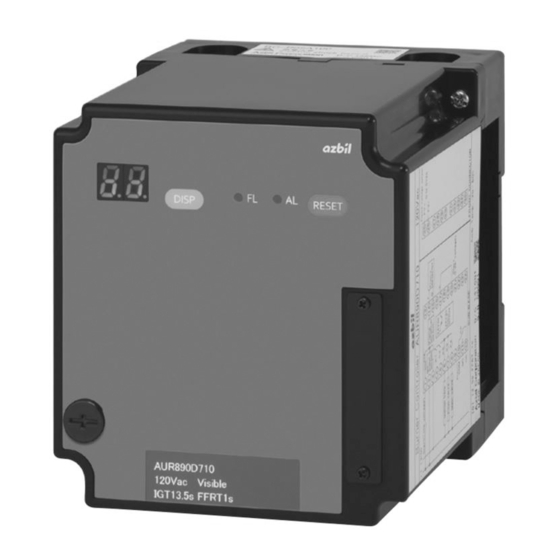
AUR890
Burner Controller
User's Manual
Thank you for purchasing the AUR890. This
manual contains information for ensuring
the correct use of the AUR890.
This manual should be read by those who
design and maintain equipment that uses
the AUR890.
It also provides necessary information
for installation, maintenance, and
troubleshooting. Be sure to keep this
manual nearby for handy reference.
Advertisement
Table of Contents

Related Manuals for Azbil AUR890


Summary of Contents for Azbil AUR890
- Page 1 No. CP-SP-1380E AUR890 Burner Controller User's Manual Thank you for purchasing the AUR890. This manual contains information for ensuring the correct use of the AUR890. This manual should be read by those who design and maintain equipment that uses the AUR890.
- Page 2 If you should find an error or omission, please contact Azbil Corporation. In no event is Azbil Corporation liable to anyone for any indirect, special or consequential damages as a result of using this product. © 2015 Azbil Corporation All Rights Reserved.
- Page 3 Conventions Used in This Manual ■ To prevent injury to the operator and others, and to prevent property damage, the following types of safety precautions are indicated: Warnings are indicated when mishandling this product might result in WARNING death or serious injury. Cautions are indicated when mishandling this product might result in CAUTION minor injury to the user, or physical damage to the product.
- Page 4 Safety Precautions WARNING Use this device with combustion equipment that is started and stopped at least once in a 24-hour period. This device cannot be used for equipment with combustion continuing for 24 hours or longer. Implement a safety design for the prepurge and external timer circuits, taking into account the safety guidelines for the equipment.
- Page 5 WARNING Do not use alarm relay output as safety output. This device has a limited product life. Beyond the product life, the risk of device failure becomes higher. Replace this device within its product life. CAUTION To ensure proper operation of this device, follow the directions given in this user's manual and in the manuals for the combustion equipment and for any other devices that are used.
-
Page 6: Table Of Contents
● When the BC-R05A100 sub-base is used (terminals 1–24 are on sub-base, 25–35 on front connector) ………………………14 ● Q890A100 base unit for RA890-AUR890 replacement ………………………………16 ● Wiring to a flame detector (UV sensor) ………………………………………………18 ● Wiring to a rectification flame rod ……………………………………………………18 ●... - Page 7 ■ Example of wiring connection with external device: Internal block diagram ………23 ● When the BC-R05A100 sub-base is used (terminals 1–24 are on sub-base, 25–35 on front connector) ……………………………………………………………23 ● Q890A100 base unit for RA890-AUR890 replacement ………………………………25 ■ Example sequence …………………………………………………………………………27 ● Normal operation (Non-recycling gas-fired combustion) …………………………27 ●...
- Page 8 Chapter 7. Specifications ■ External dimensions ………………………………………………………………………46 ● AUR890 with the BC-R05A100 sub-base ……………………………………………46 ● When combined with the Q890A100 base unit for RA890-AUR890 replacement …48...
-
Page 9: Chapter 1. Overview
Chapter 1. Overview AUR890 burner controllers were developed as an upgrade for the RA890 burner controller, and are designed for batch operation of combustion equipment (at least one start and stop in a 24-hour period). This device is used in combination with an AUD100 series Advanced Ultraviolet Flame Detector or a flame rod. -
Page 10: Instructions For Proper Use
Chapter 1. Overview (2) S tarting, running, and stopping of combustion equipment according to a predefined sequence • Operates each device according to the predefined sequence and timing. (3) Safety startup • Checks the flame detector and the flame detection circuit for flame detection error each time the start signal is issued. • Will not start the burner if a failure is detected. (4) Design that anticipates part failure modes • At startup, the self-inspection circuit errs on the side of safety if a failure is detected. -
Page 11: Model Number
Chapter 1. Overview „ Model number (Note: The dedicated sub-base and sideboard are not provided with the AUR890 controller. Order them separately.) Model number Power supply Lock-out timing Flame failure Compatible flame detector response timing AUR890F110 100 Vac 13.5 ± 1.5 s 1 s max. -
Page 12: Chapter 2. Installation, Wiring
Chapter 2. Installation, Wiring „ Installation, Precautions for wiring WARNING This device has functions that are extremely important for the safe operation of combustion equipment. Use it correctly in accordance with the user's manual. Check the model number carefully and check that the sequence timing is as specified by the combustion equipment manufacturer. -
Page 13: Installation Method
Chapter 2. Installation, Wiring CAUTION If the wires from this device exceed the recommended length, to prevent malfunction due to external electrical noise, take measures such as keeping power lines away from the input lines between the control panel and the combustion equipment. After wiring, check that the equipment is operating properly. -
Page 14: Cautions Regarding Installation
Front 50 mm 50 mm 50 mm 50 mm 80 mm AUR890 main unit 50 mm 50 mm Wiring, ducts, etc. • This device must be grounded within a grounded and conductive control panel to ensure safety. -
Page 15: When The Sub-Base (Bc-R05A100) Is Used
Chapter 2. Installation, Wiring „ When the sub-base (BC-R05A100) is used z Installation orientation Attach the device in the orientation shown below. Display area AUR890 main unit AUR890 main unit Do not install it in the orientations illustrated below. AUR890... -
Page 16: Mounting/Removing The Device And Sub-Base (Sold Separately)
Chapter 2. Installation, Wiring CAUTION Turn the power off before mounting the device on the sub-base. Otherwise, device failure may occur. z Mounting/removing the device and sub-base (sold separately) (Mounting) (1) Align the indentation in the center of the top of the device with the projection on the sub-base. -
Page 17: When The Base Unit (Q890A100) For Ra890 Replacement Is Used
Chapter 2. Installation, Wiring „ When the base unit (Q890A100) for RA890 replacement is used z Installation orientation Attach the device in the orientation shown below. AUR890 Display area main unit AUR890 main unit Do not install it in the orientations illustrated below. - Page 18 Chapter 2. Installation, Wiring (3) Insert screws into the three mounting holes in the lower part of the base unit, and tighten the screws. φ 5.5 mounting holes (3) (4) W ire the external connections to the terminal block on the lower part of the replacement base unit, and then connect the cable connectors of the upper part of the base unit to the connectors on the lower part.
-
Page 19: Terminal Numbers, Front Panel Item Names
Chapter 2. Installation, Wiring „ Terminal numbers, front panel item names Front BC-R05A100 sub-base (sold separately) Display Reset switch DISP switch Front connector cover (connector is behind cover) Jack * DIN rail clamp Terminal board * Not used (for inspection and adjustment before shipment) z Terminal No. -
Page 20: Connector For Front Wiring (81447514-001) Terminal Layout
Chapter 2. Installation, Wiring z Connector for front wiring (81447514-001) terminal layout Mounting screw Wiring Wiring fastener screw Mounting screw z Connector for front wiring (for right side wiring) (81447514-002) terminal layout Mounting screw Wiring Wiring fastener screw Mounting screw... -
Page 21: External Connection Terminals Of The Ra890 Replacement Base Unit (Q890A100)
Chapter 2. Installation, Wiring z External connection terminals of the RA890 replacement base unit (Q890A100) External connection terminals of Q890A100 Q890A100 external-connection terminal Nos. Function AC power supply (L1) AC power supply (L2 (N)) Pilot valve output Ignition transformer output Main valve output Controller (Power supply) External controller (for low... -
Page 22: Example Of Wiring Connection With External Device
When the BC-R05A100 sub-base is used (terminals 1–24 are on sub-base, 25–35 on front connector) • Non-recycling gas-fired combustion L2(N) Burner on-off circuit Limit / interlock circuit Blower operation circuit / pre-purge circuit Pre-purge completion signal AUR890/BC-R05A100 External controller *1 (for power supply) AC input circuit Combustion Power... - Page 23 Chapter 2. Installation, Wiring • Non-recycling oil-fired combustion (2-level combustion) L2(N) Burner on-off circuit Limit / interlock circuit Blower operation circuit / pre-purge circuit Pre-purge completion signal AUR890/BC-R05A100 External controller *1 (for power supply) AC input circuit Combustion Power Flame...
-
Page 24: Q890A100 Base Unit For Ra890-Aur890 Replacement
Chapter 2. Installation, Wiring z Q890A100 base unit for RA890-AUR890 replacement • Non-recycling gas-fired combustion L2(N) Burner on-off circuit Limit / interlock circuit Blower operation circuit / pre-purge circuit External controller *1 Pre-purge completion signal (for power supply) Terminal numbers of Q890A100 base unit (for RA890 replacement) - Page 25 NO output NC Alarm Terminal layout of connector : Terminal numbers of AUR890/BC-R05 for front wiring : Terminal numbers of Q890A100 base unit (for RA890 replacement) : Terminal numbers of the front connector Use the external controller for either the power...
-
Page 26: Wiring To A Flame Detector (Uv Sensor)
Chapter 2. Installation, Wiring z Wiring to a flame detector (UV sensor) • AUD100C+AUD15C Blue Terminal 14 White Terminal 15 • AUD110C+AUD15C Terminal Terminal 14 (F) Terminal 15 • AUD120C+AUD15C Blue Terminal 14 White Terminal 15 If connection of the blue and white lead wires is reversed, or if the connections to terminals F and G are reversed, the AUD15C tube unit may be damaged. -
Page 27: Example Countermeasures Against Power Surges Caused By Lightning
Chapter 2. Installation, Wiring z Example countermeasures against power surges caused by lightning When using a line surge suppressor as a countermeasure against power surges caused by lightning, connect it between Terminal 3 and the ground, as shown below. The mounting brackets of the surge suppressor are crimp-on at the grounded side and inside and in conducting state. -
Page 28: Connections To Solenoid Valve
Chapter 2. Installation, Wiring z Connections to solenoid valve WARNING Do not connect the solenoid valve to the high potential side (L1). If it is connected to L1 and a ground fault occurs, current can leak to the solenoid valve and open it, allowing fuel to flow out, regardless of the status of the burner controller. -
Page 29: Part Names
Chapter 3. Operation „ Part names Retaining screw for AUR890 main unit 7-segment LED (green) When normal: Sequence code/Flame voltage When an error occurs: Alarm code/Flame voltage DISP switch Reset switch Switch to change as follows: Switch to cancel lock-out... - Page 30 Chapter 3. Operation When an error occurs The 7-segment display shows a alarm code and the sequence code for which the alarm was issued alternately. Every time the DISP switch is pressed, the display is changed between a alarm code and the sequence code for which the alarm was issued alternately as well as the flame voltage. Alarm codes Alarm codes Sub-code Description None Interlock error Ignition failure Flame failure Switch input Internal relay feedback (K1)
-
Page 31: Example Of Wiring Connection With External Device: Internal Block Diagram
When the BC-R05A100 sub-base is used (terminals 1–24 are on sub-base, 25–35 on front connector) • Non-recycling gas-fired combustion L2(N) Burner on-off circuit Limit / interlock circuit Blower operation circuit / pre-purge circuit Pre-purge completion signal AUR890/BC-R05A100 External controller *1 (for power supply) AC input circuit Combustion Power... -
Page 32: Chapter 4. Explanation Of Operation
Chapter 4. Explanation of Operation • Non-recycling oil-fired combustion (2-level combustion) L2(N) Burner on-off circuit Limit / interlock circuit Blower operation circuit / pre-purge circuit Pre-purge completion signal AUR890/BC-R05A100 External controller *1 (for power supply) AC input circuit Combustion Power... -
Page 33: Q890A100 Base Unit For Ra890-Aur890 Replacement
Chapter 4. Explanation of Operation z Q890A100 base unit for RA890-AUR890 replacement • Non-recycling gas-fired combustion L2(N) Burner on-off circuit Limit / interlock circuit Blower operation circuit / pre-purge circuit External controller *1 Pre-purge completion signal (for power supply) Terminal numbers of Q890A100 base unit (for RA890 replacement) - Page 34 NO output NC Alarm Terminal layout of connector : Terminal numbers of AUR890/BC-R05 for front wiring : Terminal numbers of Q890A100 base unit (for RA890 replacement) : Terminal numbers of the front connector Use the external controller for either the power...
-
Page 35: Example Sequence
AUR890 stops showing the sequence code [- -]. * The AUR890 turns the main valve ON after the standby process for normal combustion. This feature does not allow the main valve to be turned on immediately after ignition in order to prevent the flame from being blown out. During the standby process for normal combustion, if the time set for external timer TM1 has passed and the contacts are reversed, the supply of power to the pilot valve and main valve may be interrupted for a moment. -
Page 36: Operation When An Ignition Failure Occurs (Non-Recycling Gas-Fired Combustion)
Power ON When approximately 8 seconds have passed after the power has been turned on, the 7-segment LED display on the front panel of the AUR890 shows the sequence code [- -]. Burner When the burner operation switch is turned... -
Page 37: Operation When A Flame Failure Occurs (Non-Recycling Gas-Fired Combustion)
Main valve : closed AUR890 will be locked out so that relays K1, K2, K3, and K4 turn OFF, the Alarm output : ON pilot and main valves close, relay K6 turns ON, and the alarm output turns ON. -
Page 38: Operation When There Is A False Flame Before Start Input (Non-Recycling Gas-Fired Combustion)
ON, a false flame check is executed during the start check. If a false flame signal lasts for 15 seconds or longer, the AUR890 will be P 1 / E 1 Alarm output : ON locked out, and relay K6 and the alarm output turn ON. -
Page 39: Normal Operation (Non-Recycling Oil-Fired Combustion (2-Level Combustion))
Power ON When approximately 8 seconds have passed after the power has been turned on, the 7-segment LED display on the front panel of the AUR890 shows the sequence code [- -]. Burner When the burner operation switch is turned... -
Page 40: Operation When An Ignition Failure Occurs (Non-Recycling Oil-Fired Combustion (2-Level Combustion))
If the flame sensor does not detect a flame within the 15 seconds of P4 / E6 Ignition transformer : stop lockout time, the AUR890 will be locked out so that relays K1, K2, K3, Fuel oil valve : closed and K5 turn OFF, the ignition transformer stops operation, the fuel oil Alarm output : ON valve closes, relay K6 turns ON, and the alarm output turns ON. -
Page 41: Operation When A Flame Failure Occurs (Non-Recycling Oil-Fired Combustion (2-Level Combustion))
Two-level fuel oil valve : closed AUR890 will be locked out. At that time relays K1, K2, K3 and K4 turn Alarm output : ON OFF, the fuel oil valve and two-level fuel oil valve close, relay K6 turns ON, and the alarm output turns ON. -
Page 42: Operation When There Is A False Flame Before Start Input (Non-Recycling Oil-Fired Combustion (2-Level Combustion))
ON, a false flame check is executed during the start check. If a false flame signal lasts for 15 seconds or longer, the AUR890 will be P 1 / E 1 Alarm output : ON locked out, and relay K6 and the alarm output turn ON. -
Page 43: Chapter 5. Trial Operation And Adjustment
Chapter 5. Trial Operation and Adjustment WARNING Make sure that the ignition times for the pilot and main burners do not exceed the ignition times specified by the burner or device manufacturer. Excessive ignition times may cause fuel to accumulate in the combustion chamber and form an explosive fuel-air mixture, which can result in a serious explosion hazard. -
Page 44: Ignition Spark Response (Uv Sensor)
Chapter 5. Trial Operation and Adjustment „ Ignition spark response (UV sensor) WARNING Ensure that the UV sensor does not detect ultraviolet rays other than those from the burner. If the UV sensor responds to other ultraviolet radiation, fuel will continue to be supplied even if the burner flame is off, potentially causing an explosion. -
Page 45: Measurement Of Flame Voltage
Chapter 5. Trial Operation and Adjustment „ Measurement of flame voltage This device shows the flame voltage on the 7-segment display. It can be checked by changing the display using the DISP switch on the front of the device. Checking the flame voltage is the best way to determine whether or not the location of the flame detector is appropriate. It should be checked during installation and servicing. Checking it once per month or more can prevent shutdowns due to insufficient flame voltage. -
Page 46: Measurement Method For Flame Voltage
The voltage can be checked on the 7-segment display or by connecting a flame meter to terminals 25 and 26 of the front connector. Analog ame meter Flame voltage display FSP136A100 * Connector for front wiring (81447514-001/002) is required to connect FSP136A100 to AUR890. Handling Precautions • For flame voltage output signal wires, use wire with indoor PVC insulation ("IV wire," JIS C3307) 0.75 mm . Wiring length cannot be more than 10 m. • The input impedance of a measuring instrument used with this device must be 100 kΩ or more. -
Page 47: Pilot Turn-Down Test
Chapter 5. Trial Operation and Adjustment „ Pilot turn-down test WARNING Make sure that the pilot turn-down test is done properly. If the flame detector is able to detect a pilot flame that is too small to ignite the main burner, and if there is a flame failure of the main burner, this device will not be able to recognize the flame failure. -
Page 48: Safety Shutoff Check
Chapter 5. Trial Operation and Adjustment Handling Precautions • If it is necessary to repeat the test, each time it is repeated be sure to stop all the equipment first to prevent an explosion and then discharge all unburned gas that has accumulated in the combustion chamber and exhaust flue. (6) Change the gas pressure from the minimum to the maximum and repeat steps (1) to (5) to check if the main burner ignites properly. -
Page 49: Chapter 6. Maintenance And Inspection
Chapter 6. Maintenance and Inspection WARNING Ensure you turn off the power of this device and all auxiliary devices when mounting, removing or connecting the wires of this device. There is a risk of electrical shock. Terminal 14 (F) retains an electrical charge even after the power is turned off. Do not touch terminal 14 (F) even after turning the power off. -
Page 50: Alarm Codes And Details
Chapter 6. Maintenance and Inspection „ Alarm codes and details When lock-out occurs, an alarm code is displayed automatically. When an alarm occurs, the sequence number and alarm code issued when the lock-out. ” Alarm code Sub-code Description Status None False flame The flame signal is detected for 15 s during pre-purge Ignition failure Ignition was not detected during the lockout time. -
Page 51: Failure Inspection Flow
Chapter 6. Maintenance and Inspection „ Failure inspection flow WARNING Before removing, mounting, or wiring the module, be sure to turn OFF the power to the module and all connected devices. Failure to do so may result in an electric shock. If there is any problem with the device, follow the inspection procedure below. - Page 52 Chapter 7. Specifications Item Description Application Batch-operated combustion systems burning gas, oil, or gas/oil mixture Compatible flame detector AUD100/110/120 series UV sensor, flame rod Sequence Lock-out timing 13.5 ± 1.5 s Standby for normal 0.4 s combustion Flame failure AUD100/110/120 series UV sensor Flame rod (Ionization) response timing *1 3 ±...
- Page 53 Chapter 7. Specifications General Structure Structure of the replacement base unit or sub-base and main unit specifications Mounted orientation Vertical or horizontal However, for horizontal attachment, 7 segment display can only be mounted so that it faces directly overhead (DIN rail mounting or direct mounting through base screw holes) Dimensions •...
- Page 54 Chapter 7. Specifications „ External dimensions z AUR890 with the BC-R05A100 sub-base (Unit: mm) • Body Sub-base (sold separately) AUR890 main unit fastening screw Sub-base Connector for (sold separately) front wiring DIN rail clamp AUR890 main unit fastening screw Model number 81447514-001 10.6...
- Page 55 Chapter 7. Specifications (Unit: mm) • Sub-base BC-R05A100 (sold separately) Knockout hole Knockout hole M3.5 (terminal screw) φ12 knockout hole φ12 knockout hole Sub-base mounting hole Sub-base mounting hole DIN rail clamp 62.5 • Sideboard 81447515-001 (sold separately) 30.7 Sub-base Sub-base φ19 knockout hole Sideboard...
- Page 56 Chapter 7. Specifications z When combined with the Q890A100 base unit for RA890-AUR890 replacement (Unit: mm) • Body AUR890 main unit fastening screw Connector for front wiring AUR890 main unit fastening screw Sideboard (in package) Screw (4) securing the upper part...
- Page 57 Chapter 7. Specifications (Unit: mm) • With the base unit (Q890A100) for RA890 replacement (purchased separately) Sideboard (in package) M4 ground screw φ23 hole (4 places) 25.5 Grommet (4 places)
- Page 59 Revision History of CP-SP-1380E Printed Edn. Revised pages Description Feb. 2015...
- Page 60 Warranty period and warranty scope 1.1 Warranty period Azbil Corporation's products shall be warranted for one (1) year from the date of your purchase of the said products or the delivery of the said products to a place designated by you.
- Page 61 Azbil Corporation's products every 5 to 10 years unless otherwise specified in specifications or instruction manuals.
- Page 62 Specifications are subject to change without notice. (09) 1-12-2 Kawana, Fujisawa Kanagawa 251-8522 Japan URL: http://www.azbil.com 1st edition: Feb. 2015 ( K )
Need help?
Do you have a question about the AUR890 and is the answer not in the manual?
Questions and answers