Table of Contents
Advertisement
No. CP-SP-1204E
™
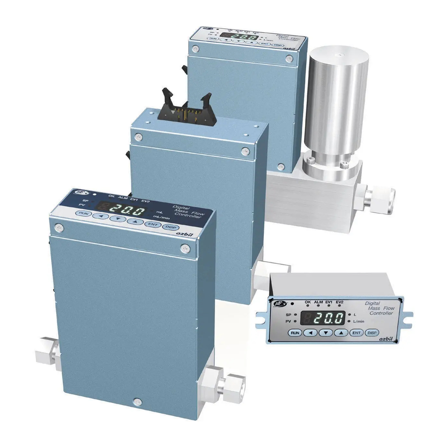
Digital Mass Flow Controller
Standard Gas Model
MQV9005/9020/9200/9500
0002/0005/0020/0050/0200/0500
User's Manual
Thank you for purchasing an Azbil
Corporation product.
This manual contains information for
ensuring the correct use of this product.
It also provides necessary information
for installation, maintenance, and
troubleshooting.
This manual should be read by those who
design and maintain equipment that uses
this product. Be sure to keep this manual
nearby for handy reference.
Advertisement
Table of Contents


Need help?
Do you have a question about the Micro Flow MQV9005 and is the answer not in the manual?
Questions and answers