Table of Contents
Advertisement
Quick Links
Advertisement
Table of Contents

Subscribe to Our Youtube Channel
Related Manuals for Fluigent LINEUP SWITCH EZ


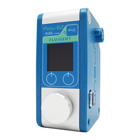
Summary of Contents for Fluigent LINEUP SWITCH EZ
- Page 1 USER’S MANUAL LINEUP SWITCH EZ...
- Page 2 It allows for the sequential delivery of up to 10 devices. Please refer all service issues to our Support department different solutions at the desired flow rate into a microfluidic chip, (support@fluigent.com) perfusion chamber or petri dish. Prevent any objects or liquid from entering the SWITCH EZ. This may cause a short-circuit or other malfunction.
-
Page 3: Table Of Contents
SWITCH EZ USER’S MANUAL QUICK START GUIDE PRODUCT OVERVIEW SETTING UP Power supply Microfluidic valve connection LineUp integration MANUAL USE Operation window Local control Hold mode SOFTWARE CONTROL LineUp Link Microfluidics Automation Tool TECHNICAL SPECIFICATIONS WARRANTY TERMS TECHNICAL SUPPORT... -
Page 4: Quick Start Guide
QUICK START GUIDE Aria is a perfusion system which automates perfusion or timed Provide power supply to the LineUp SWITCH EZ using the LineUp injection protocols. It allows for the sequential delivery of up to 10 Power Kit (P/N : LPK001) or by combining it to a supplied LineUp chain different solutions at the desired flow rate into a microfluidic chip,... - Page 5 QUICK START GUIDE Aria is a perfusion system which automates perfusion or timed Plug the Fluigent microfluidic valves to the dedicated ports. The valves injection protocols. It allows for the sequential delivery of up to 10 are automatically detected by the module and displayed on the screen...
- Page 6 QUICK START GUIDE Aria is a perfusion system which automates perfusion or timed Use the local control interface to actuate the valves or to injection protocols. It allows for the sequential delivery of up to 10 p r o g r a m s i m u l t a n e o u s o r d e r s u s i n g t h e p a u s e b u t t o n different solutions at the desired flow rate into a microfluidic chip, M-SWITCH LineUp...
- Page 7 QUICK START GUIDE Aria is a perfusion system which automates perfusion or timed To shut down the module, simply detach it from the chain by pressing the injection protocols. It allows for the sequential delivery of up to 10 « unlock » button at the top. The connected valves will shut down as well. different solutions at the desired flow rate into a microfluidic chip, user's manual starts on the next page:...
-
Page 8: Product Overview
PRODUCT OVERVIEW The LineUp SWITCH EZ is a module allowing one to control Fluigent’s microfluidic valves. The module has 6 ports and can be combined with other LineUp products such as pressure and vacuum controllers to have a complete and compact system for benchtop use. Connected microfluidic... - Page 9 PRODUCT OVERVIEW Pressure supply inlet used with pressure controllers Pressure supply transmission used with pressure controllers Operation window displays connected valves and positions Pause button used to program several orders and set them simultaneously Interface buttons to set the valves positions and validate/deny orders Rotative dial to navigate and to select the valve on which operate Power and data transmission...
-
Page 10: Setting Up
SETTING UP Power supply LineUP To provide power supply to the module, use the Power kit LineUp supply kit (P/N : LPK001) or the (P/N : SWITCH EZ LU-SPK-0002). The will start and display the connected valve information on the operation window. To wall socket If the module is combined to other powered LineUp modules,... -
Page 11: Microfluidic Valve Connection
SETTING UP Microlfuidic valves connection Plug the Fluigent microfluidic valves to the dedicated ports at the top of the SWITCH EZ. Once the valves are connected, and once the SWITCH EZ is powered ON, the module displays the information of the correspunding valves on the operation window. - Page 12 Simply stack a module to another and benefit from a single power supply source or pressure source for the whole chain. If a LINK is connected to a PC, one can access to Fluigent Microfluidics Automation Tool and program pressure or flow rate orders as well as valve actuation timing.
-
Page 13: Manual Use
MANUAL USE Operation window SWITCH One can control and actuate microfluidics valves directly on the local control interface operation window. using the and the Pause button Port 6 information for hold mode (p.17) Port 1 information Left button action Port 2 information Right button action Port 3 information Left button... -
Page 14: Local Control
MANUAL USE Local control Fluigent microfluidic valves can be actuated without a PC by using the SWITCH EZ local control. Once a valve is connected to a port, its information is displayed on the module and one can control it directly. - Page 15 To switch from a position to another, click on the corresunding button. The valve will immediately go to the selected position and display it on screen. The Fluigent 2-SWITCH has also a local button at the top of the valve which can be used as well to switch the valve position.
- Page 16 MANUAL USE SWITCH EZ can support 6 valves with a limitation of 3 rotary valves. Each port is universal and correspund to a section on the operation window. L-SWITCH 2-SWITCH SWITCH EZ...
-
Page 17: Hold Mode
MANUAL USE Hold mode If one wants to switch several valves at the same time, the pause button at SWITCH EZ allows to enter the "hold mode". During this the top right of the phase, the selection square on the screen will become red and each order defined on the valves positions will be recorded but not applied. -
Page 18: Software Control
SOFTWARE CONTROL LineUp Link LineUp Link allows to connect the LineUp series modules to a computer. T h e L i n k a l l o w s t h e L i n e U p s y s t e m t o b e n e f i t f u l l advanced func tionalities f rom F l u i g e n t ' s s o f twa re suite. -
Page 19: Microfluidics Automation Tool
SOFTWARE CONTROL Microfluidics Automation Tool Fluigent Microfluidics Automation Tool is a software to write protocols by defining the devices behavior and timing. To do so, the MAT interface allows one to drag and drop functions regarding the connected instruments, and order the steps onto a worksheet by linking them in a specific order and indicating timing for those steps. - Page 20 SOFTWARE CONTROL Here are examples of MAT protocols to have an overview of the specific functions of each Fluigent microfluidic valve. 2-SWITCH will toggle position, then wait for In this protocol, the 1 min 30 sec, and toggle position again.
-
Page 21: Technical Specifications
TECHNICAL SPECIFICATIONS Valve requirements 2-SWITCH Up to six Up to three rotary valves: Maximum valves supported M-SWITCH L-SWITCH Hardware specifications Dimensions 91,9 x 71,8 x 131 mm Weight 317 g Electrical specifications Electrical consumption 2A peak LineUp Power Kit (LPK001) Power supply LineUp Supply Kit (LU-SPK-002) -
Page 22: Warranty Terms
What this warranty covers This warranty is granted by Fluigent and applies in all countries. The Fluigent product is guaranteed for one year from the date of delivery at the laboratory against defects in materials and workmanship. If found to be defective within the warranty period, the Fluigent product will be repaired or replaced free of charge. -
Page 23: Technical Support
+33 1 77 01 82 65 Fluigent Inc. +1 (978) 934 5283 Fluigent GmbH +49 3641 277 652 For a fully detailed FAQ for all Fluigent products, please visit: http://www.fluigent.com/faqs/ Interested in Fluigent products ? complete Fluigent product line application... - Page 24 VERSION MAR. 2021...
Need help?
Do you have a question about the LINEUP SWITCH EZ and is the answer not in the manual?
Questions and answers