
Subscribe to Our Youtube Channel
Related Manuals for Fluigent ESS SWITCHBOARD


Summary of Contents for Fluigent ESS SWITCHBOARD
- Page 1 User Manual ESS™ platform: SWITCHBOARD, M-SWITCH™, L-SWITCH™ and 2-SWITCH™ Version 10A...
-
Page 2: Table Of Contents
INTRODUCTION FLUIDIC CIRCUITS EXAMPLES USING A 2-SWITCH™ VALVE Fluidic principle Description 3.2.1 2-SWITCH™ Front 3.2.2 2-SWITCH™ Back 3.2.3 2-SWITCH™ Top and Bottom faces Connection 3.3.1 Fluidic connection 3.3.2 Electric connection Positioning USING AN M-SWITCH™ VALVE Fluidic principle Description 4.2.1 M-SWITCH™ Front and top 4.2.2 M-SWITCH™... - Page 3 Connection HOW TO USE THE 2-SWITCH™, M-SWITCH™ AND L-SWITCH™ WITH GAS HOW TO START WORKING WITH THE ESS™ FREQUENTLY ASKED QUESTIONS SPECIFICATIONS Page - 3...
- Page 4 What This Warranty Covers This warranty is granted by Fluigent and applies in all countries. Your Fluigent product is guaranteed for one year from the date of delivery at your laboratory against defects in materials and workmanship. If found to be defective within the warranty period, your Fluigent product will be repaired or replaced free of charge.
- Page 5 WARNINGS: Do never open SWITCHBOARD, 2-SWITCH™, L-SWITCH™ and M-SWITCH™ devices. Refer all servicing to after-sales service department (support@fluigent.com). Prevent any objects or liquids from entering the SWITCHBOARD, this may cause a short-circuit failure or other malfunction. Failing to respect this advice would:...
-
Page 6: Introduction
The ESS™ platform has been designed to work at its best performances with FLUIGENT flow control solutions (MFCS™ and Flow-Rate Platform). It is however possible to use the ESS™ platform with other flow control systems provided that the pressure applied to the ESS™... -
Page 7: Fluidic Circuits Examples
2. Fluidic circuits examples Page - 7... -
Page 8: Using A 2-Switch™ Valve
3. Using a 2-SWITCH™ valve 3.1 Fluidic principle The 2-SWITCH™ is a 3-port / 2-position valve. This means that three (3) ports can be connected with fittings and tubings to your application, and that it is possible to choose between two (2) positions linking the ports in two (2) different manners. -
Page 9: Description
3.2 Description 3.2.1 2-SWITCH™ Front Here is a picture of the front of a 2-SWITCH™. The 3 fluidic ports are at the bottom part of the device. The common port is the central port, included in the device front. When looking at the front of the 2- SWITCH™, port #1 is the right port and port #2 is the left one. -
Page 10: 2-Switch™ Back
SWITCHBOARD). Other types of cable can damage the ESS™, and reciprocally, the cables provided with the ESS™ should not be used for other applications. FLUIGENT advises to only use the cables provided with the ESS™ for ESS™ operation. Orange indicator... -
Page 11: 2-Switch™ Top And Bottom Faces
3.2.3 2-SWITCH™ Top and Bottom faces Top face Here is a picture of the top face of a 2-SWITCH™. A UNC ¼-20’’ thread is inserted in the centre of the top face so that the 2-SWITCH™ can be fastened to the provided base or to any ¼-20’’ screw-mounted device (as further explained in §3.4). -
Page 12: Connection
2-SWITCH™ and give non-tight fluidic connection. NB: When the 2-SWITCH™ is not used or stored, FLUIGENT advises you to connect plugs to all ports to protect the fluidic ports from dust. - Page 13 NB: the nuts and ferrules are specifically designed to work together. FLUIGENT advises you to only associate the provided ferrules with the provided nuts and vice-versa. 4. Insert the assembly into the receiving port,...
- Page 14 5. To check the tightness of your connection, you may pull gently on the tubing: it must stay fitted in the ferrule and nut. Connecting a plug to the 2-SWITCH™ 1. Simply screw the plug in port #1 or port #2 finger-tight.
-
Page 15: Electric Connection
2-SWITCH™ with the SWITCHBOARD). Other types of cable can damage the ESS™, and reciprocally, the cables provided with the ESS™ should not be used for other applications. FLUIGENT advises to only use the cables provided with the ESS™ for the ESS™. -
Page 16: Positioning
3.4 Positioning There are several possibilities to set the 2-SWITCH™ up. Please note that the 2-SWITCH™ device does not have any imposed mounting orientation. The 2-SWITCH™ can be used in any spatial configuration. Setting-up with the provided base The base provided with the 2-SWITCH™ can be screwed to any of its ¼-20’’... - Page 17 As many 2-SWITCH™ as you need can be assembled together horizontally, meanwhile can be set-up on their base fastened into their back insert. 2-SWITCH™ devices can also be assembled vertically. FLUIGENT advises not to assemble more than two 2-SWITCH™ together vertically. Page - 17...
- Page 18 Other possible setting-up The three ¼-20’’ inserts of the 2-SWITCH™ can be used to mount the 2-SWITCH™ on any frame or support equipped with ¼-20’’ pins such as a flexible rod as shown here (not provided with the 2-SWITCH™). ¼-20’’ thread is also the standard for all photographic equipment.
-
Page 19: Using An M-Switch™ Valve
4. Using an M-SWITCH™ valve 4.1 Fluidic principle The M-SWITCH™ is an 11-port / 10-position valve. This means that eleven (11) ports can be connected with tubings, and that it is possible to choose between ten (10) positions linking one of the ten (10) external ports to the central port of the valve. -
Page 20: Description
4.2 Description 4.2.1 M-SWITCH™ Front and top Here is a picture of the front of an M-SWITCH™. At the top of the picture, the fluidic head of the device can be seen. The head holds the fluidic ports. The head of the M-SWITCH™ is made up of the Ram which holds the integrated fittings and the Spanner, which is tightened around the Ram to clench the integrated fittings and make tight fluidic connections. -
Page 21: M-Switch™ Back
4.2.2 M-SWITCH™ Back Here are pictures of the back of an M-SWITCH™. At the bottom of the device we can see the RJ45 port to connect electrically the M-SWITCH™ to the SWITCHBOARD. Two light indicators are associated with the RJ45 port. The orange indicator lights up when the M- SWITCH™... -
Page 22: Connection
M-SWITCH™ and give non-tight fluidic connection. NB: When the M-SWITCH™ is not used or stored, FLUIGENT advises you to cover the M-SWITCH™ with the red cap to protect the fluidic ports from dust.. - Page 23 1. Cut the 1/16’’ OD tubing to the desired length, leaving a square-cut face. For connecting a plug, take one of the plugs provided by Fluigent. 2. Mark each piece of tubing or plug 24mm from the end (it will be an indicator to ensure that the tubing is fully seated).
- Page 24 4. Insert the piece of tubing or plug in one port and push it all the way to the bottom of the port. The mark made at step 2 should be approximately flush with the top of the Ram when tubing is fully seated.
-
Page 25: Electric Connection
M-SWITCH™ with the SWITCHBOARD). Other types of cable can damage the ESS™, and reciprocally, the cables provided with the ESS™ should not be used for other applications. FLUIGENT advises to only use the cables provided with the ESS™ for the ESS™. -
Page 26: Positioning
4.4 Positioning There are several possibilities to set the M-SWITCH™ up. Please note that the M-SWITCH™ device does not have any imposed mounting orientation. The M-SWITCH™ can be used in any spatial configuration. Vertical position The M-SWITCH™ can be set up vertically. As explained in §4.2.3, a pad covers the bottom face to ensure a good gripping of the M-SWITCH™... - Page 27 ¼-20’’ thread is also the standard for all photographic equipment. You can use for example a tripod for cameras and screw an M-SWITCH™ on it (not provided with the M-SWITCH™). Page - 27...
-
Page 28: Using An L-Switch™ Valve
5. Using an L-SWITCH™ valve 5.1 Fluidic principle The L-SWITCH™ is a 6-port / 2-position valve for injection or switching different fluids controlled by our ESS Control software. Fluidic switching mode Here is the fluidic diagram of an L-SWITCH™. The L- SWITCH™... -
Page 29: Description
The head of the L-SWITCH™ is made up of the Ram which holds the fluidics ports and a Spanner. Fluigent provides you external fittings to make tight fluidic connections. The method to connect tubings to the L-SWITCH™ is detailed in §5.3.1. -
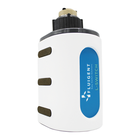
Page 30: L-Switch™ Back
5.2.2 L-SWITCH™ Back Here are pictures of the back of an L-SWITCH™. At the bottom of the device we can see the white RJ45 port to connect electrically the L-SWITCH™ to the SWITCHBOARD. Two light indicators are associated with the RJ45 port. The orange indicator lights up when the L- SWITCH™... -
Page 31: Connection
These fittings have been specifically selected by FLUIGENT to ensure good L-SWITCH™ operation. FLUIGENT advises you to use only these fittings on the L- SWITCH™. NB: When the L-SWITCH™ is not used or stored, FLUIGENT advises you to cover the L-SWITCH™ with the red cap to protect the fluidic ports from dust. Page - 31... - Page 32 Connecting a 1/16’’ OD tubing to the L-SWITCH™ Cut the 1/16’’ OD tubing to the desired length, leaving a square-cut face. Insert the tubing into a nut until it passes 1.5 - 3mm Insert into a port of L-SWITCH™, twist until it is tightened. You can pull gently the tubing to verify that it is securely connected to the port.
- Page 33 Connecting a plug to the L-SWITCH™ Before using the L-SWITCH™ in your fluidic circuit, if there are still unclosed ports after connecting all your tubing, you need to close them with blue plugs. Twist the blue plug until it is tightened Page - 33...
- Page 34 (nuts and ferrules are provided with the sample loop). You have a large selection of sample loops of different volumes. Please contact Fluigent for more information. Pass one end of the sample loop through a nut Add a ferrule Hold the set together and insert it into a port of the L-SWITCH™...
- Page 35 Repeat these steps for the other end of the sample loop to connect it to another port of the L- SWITCH™ (for example port 4 here) Example of using the sample loop with a syringe injector The objective of using sample loop is to introduce a precise volume of liquid into a fluidic circuit. In this example, the fluid circuit enters from the port 2 and exits from the port 3.
- Page 36 Connecting a syringe injector to the L-SWITCH™ The syringe is often used with a sample loop in order to fill up the sample loop. (See the example above) You need to use the provided adaptor to connect a syringe injector to the L-SWITCH™ Unscrew the adaptor set to separate the nut from the adaptor...
-
Page 37: Electric Connection
L-SWITCH™ with the SWITCHBOARD). Other types of cable can damage the ESS™, and reciprocally, the cables provided with the ESS™ should not be used for other applications. FLUIGENT advises to only use the cables provided with the ESS™ for the ESS™. -
Page 38: Positioning
5.4 Positioning There are several possibilities to set the L-SWITCH™ up. Please note that the L-SWITCH™ device does not have any imposed mounting orientation. The L-SWITCH™ can be used in any spatial configuration. Vertical position The L-SWITCH™ can be set up vertically. As explained in §5.2.3, a pad covers the bottom face to ensure a good gripping of the L-SWITCH™... - Page 39 ¼-20’’ thread is also the standard for all photographic equipment. You can use for example a tripod for cameras and screw an L-SWITCH™ on it (not provided with the L- SWITCH™). Page - 39...
-
Page 40: Using The Switchboard
6. Using the SWITCHBOARD The SWITCHBOARD is absolutely necessary to operate the ESS™. This device hosts up to four (4) M-SWITCH™ or L-SWITCH™ and eight (8) 2-SWITCH™ and provides them power supply. The SWITCHBOARD is also the link between the connected 2-SWITCH™, M-SWITCH™, L-SWITCH™ and the controlling software ESS™ Control (cf. ESS™ Control User Manual). -
Page 41: Connection
Warning: Please note that the power supply provided with the ESS™ has been carefully selected to meet the power requirements of the ESS™ in all configurations and to comply with all safety standards. FLUIGENT advises to only use the power supply provided with the ESS™ for the ESS™. - Page 42 To connect an M/L-SWITCH™ to the SWITCHBOARD, plug one end of a white RJ45 cable provided with the ESS™ to one of the four (4) M/L-SWITCH™ RJ45 ports on the SWITCHBOARD, and the other end to the RJ45 port of the M/L-SWITCH™ (cf. §4.3.2 and §5.3.2). When the SWITCHBOARD is powered on (cf.
-
Page 43: How To Use The 2-Switch™, M-Switch™ And L-Switch™ With Gas
7. How to use the 2-SWITCH™, M-SWITCH™ and L-SWITCH™ with gas Here is an example of how you can use the 2-SWITCH™, M-SWITCH™ or L-SWITCH™ with gas. We present the fittings and tubes and describe how to use it to connect in air the MFCS™-EZ to the 2-SWITCH™/M-SWITCH™/L- SWITCH™. - Page 44 Connecting the reservoir to the MFCS™-EZ via the 2-SWITCH™, the M-SWITCH™ and the L-SWITCH™ Once the connection has been done between the fluidic tube and the pressure tube, you can use the assembly to connect the 2-SWITCH™/M-SWITCH™/ L-SWITCH™ to the MFCS™-EZ and the 2-SWITCH™/M-SWITCH™/ L- SWITCH™...
- Page 45 Warning: - After your experiment, do not forget to wash your M-SWITCH™, L-SWITCH™ or 2-SWITCH™ with distilled water and then isopropanol, to avoid any clogging in the fluidic parts that could damage the device and cause malfunction. - The use of 2-SWITCH™ and/or M-SWITCH™ and /or L-SWITCH™ with gas reduces the lifetime of the valves and can lead to a premature aging.
-
Page 46: How To Start Working With The Ess
8. How to start working with the ESS™ Here is a quick-setup guide to remind you of the main steps to get your ESS™ platform up and running: 1. Firstly, you may want to do the required fluidic connections on the 2-SWITCH™ , M-SWITCH™ and L- SWITCH™... -
Page 47: Frequently Asked Questions
9. Frequently Asked Questions §3.1 With a fluidic “on/off” switch configuration, should I fill with liquid the plugged path inside the 2-SWITCH™ before screwing the plug? If you are planning to use a 2-SWITCH™ as a fluidic on/off switch, you will need to plug either port #1 or port #2 on the 2-SWITCH™. -
Page 48: Specifications
Weight 419 g L-SWITCH™ Please note that the ESS™ platform have been optimized to work with FLUIGENT flow control devices. If you are using the ESS™ Pressure rating 100 psi platform with other flow control systems, please check that the pressure in your fluidic system does not exceed 100 psi. - Page 49 FLUIGENT SA O’kabé bureaux 55-77 Avenue de Fontainebleau 94270 Le Kremlin-Bicêtre FRANCE Tel: +331 77 01 82 68 Fax : +331 77 01 82 70 www.fluigent.com Technical support: support@fluigent.com Tel: +331 77 01 82 65 General information: contact@fluigent.com Page - 49...
Need help?
Do you have a question about the ESS SWITCHBOARD and is the answer not in the manual?
Questions and answers