Table of Contents
Advertisement
Quick Links
Advertisement
Table of Contents

Subscribe to Our Youtube Channel
Related Manuals for Fluigent LINEUP SWITCH EZ


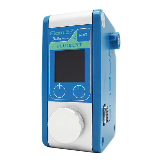
Summary of Contents for Fluigent LINEUP SWITCH EZ
- Page 1 USER’S MANUAL LINEUP SWITCH EZ...
- Page 2 PRECAUTIONS Do not open SWITCH EZ, 2-SWITCH , M-SWITCH or L-SWITCH Aria is a perfusion system which automates perfusion or timed injection protocols. It allows for the sequential delivery of up to devices. Please refer all service issues to our Support department 10 different solutions at the desired flow rate into a microfluidic (support@fluigent.com) chip, perfusion chamber or petri dish.
-
Page 3: Table Of Contents
SWITCH EZ USER’S MANUAL QUICK START GUIDE PRODUCT OVERVIEW SETTING UP Power supply Microfluidic valve connection LineUp integration MANUAL USE Operation window Local control Hold mode SOFTWARE CONTROL LineUp Link OxyGEN REMOTE OPERATION TECHNICAL SPECIFICATIONS WARRANTY TERMS TECHNICAL SUPPORT... -
Page 4: Quick Start Guide
QUICK START GUIDE Provide power supply to the LineUp SWITCH EZ using the LineUp Power Kit (P/N : LPK001) or by combining it to a supplied LineUp chain LineUp Power LineUp SWITCH EZ LineUp Supply Kit LineUp LINK LineUp FlowEZ LineUp SWITCH EZ... - Page 5 QUICK START GUIDE Plug the Fluigent microfluidic valves to the dedicated ports. The valves are automatically detected by the module and displayed on the screen M-SWITCH LineUp system The LineUp SWITCH EZ is compatible with Fluigent microfluidic valves: 2-SWITCH : 3-port/2-way (2SW002)
- Page 6 If one wishes to automate the valve actuation timing, connect the LineUp injection protocols. It allows for the sequential delivery of up to chain to a PC using the LineUp LINK and process on Fluigent OxyGEN 10 different solutions at the desired flow rate into a microfluidic OxyGEN...
- Page 7 QUICK START GUIDE Aria is a perfusion system which automates perfusion or timed To shut down the module, simply detach it from the chain by pressing injection protocols. It allows for the sequential delivery of up to the « unlock » button at the top. The connected valves will shut down 10 different solutions at the desired flow rate into a microfluidic user's manual starts on the next page:...
-
Page 8: Product Overview
PRODUCT OVERVIEW The LineUp SWITCH EZ is a module allowing one to control Fluigent’s microfluidic valves. The module has 6 ports and can be combined with other LineUp products such as pressure and vacuum controllers to have a complete and compact system for benchtop use. Connected microfluidic valves can be controlled or programmed either by using the... - Page 9 PRODUCT OVERVIEW Pressure supply inlet used with pressure controllers Pressure supply transmission used with pressure controllers Operation window displays connected valves and positions Pause button used to program several orders and set them simultaneously Interface buttons to set the valves positions and validate/deny orders Rotative dial to navigate and to select the valve on which operate Power and data transmission...
-
Page 10: Setting Up
SETTING UP To provide power supply to the module, use the LineUP Power kit (P/N : LPK001) or the LineUp supply kit (P/N : LU -S PK- 0 0 02 ) . T h e S WI TC H E Z w i l l s t a r t a n d d i s p l ay the connected valve information on the operation window. - Page 11 SETTING UP Plug the Fluigent microfluidic valves to the dedicated ports at the top of the SWITCH EZ. Once the valves are connected, and once the SWITCH EZ is powered ON, the module displays the information of the correspunding valves on the operation window.
-
Page 12: Lineup Tm Integration
Simply stack a module to another and benefit from a single power supply source or pressure source for the whole chain. If a LINK is connected to a PC, one can access to Fluigent OxyGEN and program pressure or flow rate orders as well as valve actuation timing. -
Page 13: Manual Use
MANUAL USE One can control and actuate microfluidics valves directly on the SWITCH using the local control interface and the operation window. Pause button Port 6 information for hold mode (p.17) Port 1 information Left button action Port 2 information Right button action Port 3 information Left button... -
Page 14: Local Control
MANUAL USE Fluigent microfluidic valves can be actuated without a PC by using the SWITCH EZ local control. Once a valve is connected to a port, its information is displayed on the module and one can control it directly. If no microfluidic valve is... - Page 15 To switch from a position to another, click on the corresunding button. The valve will immediately go to the selected position and display it on screen. The Fluigent 2-SWITCH has also a local button at the top of the valve which can be used as well to switch the valve position.
- Page 16 MANUAL USE SWITCH EZ can support 6 valves with a limitation of 3 rotary valves. Each port is universal and correspund to a section on the operation L-SWITCH 2-SWITCH SWITCH EZ...
-
Page 17: Hold Mode
MANUAL USE If one wants to switch several valves at the same time, the pause button at the top right of the SWITCH EZ allows to enter the "hold mode". During this phase, the selection square on the screen will become red and each order defined on the valves positions will be recorded but not applied. -
Page 18: Software Control
SOFTWARE CONTROL LineUp Link allows to connect the LineUp series modules to a computer. T h e L i n k a l l o w s t h e L i n e U p s y s t e m t o b e n e f i t f u l l advanced func tionalities f rom F l u i g e n t ' s s o f twa re suite. -
Page 19: Oxygen
SOFTWARE CONTROL Fluigent’s OxyGEN software is a complete interface allowing one to control, monitor and automate Fluigent product line. This dedicated dashboard can be used as a tool for real-time control of pressures, flow rates and valve actuation in microfluidic experiments. Its modular interface is designed for independent and simultaneous monitoring of all instruments and channels. - Page 20 SOFTWARE CONTROL Here are examples of OxyGEN protocols to have an overview of the specific functions of each Fluigent microfluidic valve. In this protocol, the 2-SWITCH will toggle position, then wait for 1 min 30 sec, and toggle position again.
-
Page 21: Remote Operation
REMOTE OPERATION T h e f o l l o w i n g p a r t d e t a i l s t h e s e r i a l R S - 2 3 2 c o m m u n i c a t i o n i n f o r m a t i o n f o r t h e u s e o f t h e L i n e U p S W I T C H E Z w i t h t h e L I N K C O M . - Page 22 REMOTE OPERATION This remote command set is the default set available on the instrument. All commands must be terminated with a <CR>. All decimal values use the point “.” as decimal separator. A query command ends with a question mark “?” for queries. The data column represents the response of the instrument.
- Page 23 REMOTE OPERATION The following table describes the SWITCH EZ remote commande set: Query Data Function / Response SWEZ Returns informations about the valve at index X (position on the LineUP chain) in port Y of the SwitchEZ type = "2SW", "MSW", "LSW" or "N/C" respectively for 2-Switch, M-Switch, <type>...
-
Page 24: Technical Specifications
TECHNICAL SPECIFICATIONS Valve requirements Up to six 2-SWITCH Up to three rotary valves: Maximum valves supported M-SWITCH L-SWITCH Hardware specifications Dimensions 91,9 x 71,8 x 131 mm Weight 317 g Electrical specifications Electrical consumption 2A peak LineUp Power Kit (LPK001) Power supply LineUp Supply Kit (LU-SPK-002) -
Page 25: Warranty Terms
Arrange a mutually convenient time for Fluigent service representative to discuss and find a solution to fix the issue. Repairs will be made remotely whenever possible. If more action is needed, the system will need to be sent back to Fluigent offices (for no additional cost, only if it is under warranty). Warranty conditions... -
Page 26: Technical Support
+33 1 77 01 82 65 Fluigent Inc. +1 (978) 934 5283 Fluigent GmbH +49 3641 277 652 For a fully detailed FAQ for all Fluigent products, please visit: http://www.fluigent.com/faqs/ Interested in Fluigent products ? To view the complete Fluigent product line... - Page 27 VERSION JUN. 2023...
Need help?
Do you have a question about the LINEUP SWITCH EZ and is the answer not in the manual?
Questions and answers