
Subscribe to Our Youtube Channel
Related Manuals for infobit iSwitch 265


Summary of Contents for infobit iSwitch 265
- Page 1 265 2K60 over IP 100M/1GbE with Video Wall Processing www.infobitav.com info@infobitav.com VER 1.0...
-
Page 2: Table Of Contents
Thank you for purchasing this product For optimum performance and safety, please read these instructions carefully before connecting, operating or adjusting this product. Please keep this manual for future reference. Surge protection device recommended This product contains sensitive electrical components that may be damaged by electrical spikes, surges, electric shock, lighting strikes, etc. -
Page 3: Introduction
1. Introduction This AV over IP product distributes multiple HD contents to multiple HD display devices over a 100M/1G Network Switch. It offers configurable high quality, low-bandwidth H.265/H.264 configurable compression video and supports resolution up to 1920x1200@60Hz 4:4:4. Signal transmission distance can be extended up to 328ft/100m via CAT5E/6/6A/7 cable. -
Page 4: Package Contents
3. Package Contents Item Item 2K60 over IP 100M/1GbE 2K60 over IP 100M/1GbE Encoder Decoder 3-pin Phoenix Connector 3-pin Phoenix Connector (3.81mm, male) (3.81mm, male) IR Blaster Cable (1.5 meters) IR Blaster Cable (1.5 meters) IR Receiver Cable (1.5 meters) IR Receiver Cable (1.5 meters) Machine Screw (KM3, 4mm) Machine Screw (KM3, 4mm) - Page 5 Connection 1x HDMI IN [Type A, 19-pin female] 1x HDMI OUT [Type A, 19-pin female] 1x AUDIO IN [3-pin phoenix connector] 1x AUDIO OUT [3-pin phoenix connector] 1x RS-232 [3-pin phoenix connector] Encoder 1x LAN [RJ45 connector, POE] 1x IR IN [3.5mm audio jack, 12V IR] 1x IR OUT [3.5mm audio jack, 12V IR] 1x USB Host [Type B, 4-pin female] 2x USB Devices [Type A, 4-pin female]...
-
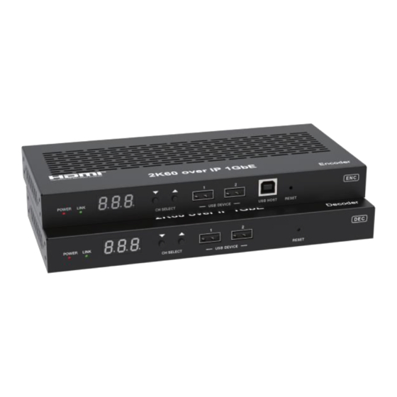
Page 6: Operation Controls And Functions
5. Operation Controls and Functions 5.1 Encoder Panel POWER LINK CH SELECT USB HOST RESET USB DEVICE L R TX RX HDMI IN HDMI OUT IN AUDIO OUT RS-232 IR IN IR OUT DC 12 V 17 16 14 15 Name Function Description POWER LED... - Page 7 IR OUT IR signal output port. 5/22...
- Page 8 12V IR signal input port. IR IN RS-232 serial port, supporting signal pass-through and local RS-232 serial port control. AUDIO IN: Analog stereo audio input port. Connect to an audio input source device. IN-AUDIO-OUT AUDIO OUT: Analog stereo audio output port. Connect to an audio output device.
- Page 9 4, For Channel ID settings, press the UP or DOWN button to display the current ID number (e.g. 001) on the LED screen. Press and hold UP + DOWN buttons for 5 seconds, then release to enter the “ID Settings” mode. The ID number (e.g. 001) on the LED screen will flash at 1Hz, then press the UP or DOWN button to select the Channel ID you desired, then press and hold UP + DOWN buttons for 5 seconds to confirm the setting and stop flashing.
-
Page 10: Decoder Panel
5.2 Decoder Panel POWER LINK CH SELECT USB DEVICE RESET L R TX RX HDMI OUT AUDIO OUT RS-232 IR IN IR OUT DC 12 V 14 12 13 Name Function Description POWER LED The LED flashes at 1 Hz during the system startup, and the (Red) LED is always on after the startup is complete. - Page 11 HDMI output port, connect to an HDMI display device such as HDMI OUT TV or monitor. 100M/1G Network port. Connect to a Switch/Router/Hub for LAN (POE) data transmission or POE function. Link Signal ▪ Illuminating: The network cable is connected normally. Indicator lamp ▪...
- Page 12 The corresponding output resolution ID is as follows: Resolution ID Resolution Description Pass Through (default) 1080P60 1080P50 1080P30 1080P25 1080P24 720P60 720P50 576P50 480P60 640X480P60 800X600P60 1024X768P60 1280X800P60 1280X1024P60 1366X768P60 1440X900P60 1600X1200P60 1680X1050P60 1920X1200P60 10/22...
-
Page 13: Rack Mounting Instruction
6. Rack Mounting Instruction 6.1 6U Rack Mounting This product can be mounted in a standard 6U rack (Please contact your supplier for 6U rack sale). The mounting steps are as follows: Step 1: Use included screws to fix two mounting ears on the product, as shown in the figure below: Step 2: Insert the product with mounting ears into a 6U rack (up to 10 units can be installed vertically), as shown in the figure below:... -
Page 14: Rack Mounting
Step 3: Use screws to fix mounting ears on the rack to complete the mounting, as shown in the figure below: 6.2 1U Rack Mounting This product also can be mounted in a standard 1U rack (up to 4 units can be installed horizontally). -
Page 15: Encoder And Decoder Matching Settings
Step 2: Fix two 1U rack panels on another two stacked products in the same way, then use screws to fix two 1U rack panels together, as shown in the figure below: Step 3: Fasten screws between two 1U rack panels, so that four products are mounted in a 1U rack, as shown in the figure below: 7. - Page 16 Method 1: Use the CH SELECT buttons on the front panel of the Encoder/ Decoder. Accoding to the methods metioned in Chapter 5, set the ID of Encoder, then set the ID of Decoder, finally set the Encoder ID from which to subscribe the stream.
-
Page 17: Web Gui User Guide
8. Web GUI User Guide You can use the built-in Web GUI to configure all IP products through a Switch. The operation method is shown as below. Step 1: Match all Encoders and Decoders as described in Chapter 7. Step 2: Connect the PC, Encoders and Decoders you need to configure to a Switch. - Page 18 16/22...
- Page 19 Step 3: Press and hold the (CH SELECT) UP button on the front panel of the Encoder/Decoder for 5 seconds to check the IP address. (Please refer to Chapter 5 for details.) Step 4: Set the PC’s IP address to be in the same network segment with the Encoder/Decoder, for instance, set the IP address to be 169.254.3.150 and Subnet mask to be 255.255.0.0.
- Page 20 The Web GUI function pages are shown as below: ■ Device Information Page The Status page provides basic information about the Encoder/Decoder, such as Firmware Version, IP Address, Subnet Mask, Gateway and MAC Address. ■ Video Configuration Page On this page, you can configure the video properties as required. 18/22...
- Page 21 Encoder Video Configuration Encoder video configuration page includes Main Stream, Sub Stream, ID Setting, Audio Selection and EDID Setting. Main Stream: You can configure Video Encoding Format, Audio Encoding Format and Bitrate. Video Encoding Format supports H.264 and H.265. Audio Encoding Format supports PCM and AAC. Sub Stream: You can configure Video Encoding Format, Resolution and Bitrate.
- Page 22 User EDID 1 and User EDID 2 can be uploaded in Select User EDID1 File and Select User EDID2 File, and the content of the uploaded binary file is EDID. (This file can be downloaded from the Download EDID of the Decoder Video page.) Decoder Video Configuration Decoder video configuration page includes Trasmission Protocol, Scale...
- Page 23 Transmission Protocol: You can select “udp unicast” or “udp multicast”. Scaler Setting: You can set the output resolution. Download EDID: You can download the EDID binary file of the display device connected to the Decoder. The EDID file can be used as the User EDID file to be uploaded to the Encoder.
- Page 24 Notes: (1) The Network Settings can be set only when the Mode button is set to Static. (2) All changes will take effect by clicking “Save” below. (3) After any changes to the Network Settings, username or Login Password, it will redirect to the Web browser home page or the Web GUI login interface. You need to log in the Web GUI again with the new settings.
-
Page 25: Switch Model
■ Log Out Page Click “Log Out” on the left, the Web GUI will exit and skip to the login interface automatically. 9. Switch Model A network Switch used to set up the system should support below features: 1. Type of layer 3/managed network Switch. 2. - Page 26 24/22...
- Page 27 Notes: (1) For the default IP mode of Control LAN port of the Controller Box is DHCP, the PC also needs to be set to “Obtain an IP address automatically” mode, and a DHCP server (e.g. network router) is required in the system. (2) If there is no DHCP server in the system, 192.168.0.225 will be used as the IP address of Control LAN port.
Need help?
Do you have a question about the iSwitch 265 and is the answer not in the manual?
Questions and answers