
Subscribe to Our Youtube Channel
Related Manuals for Seagate OneStor SP-3584


Summary of Contents for Seagate OneStor SP-3584
- Page 1 OneStor® SP-3584 Installation & User Guide Part No. 83-00007099-10-01 Revision B June 2017...
- Page 2 No part of this document may be transmitted or copied in any form, or by any means, for any purpose, without the written permission of the Authors. Revision B June 2017 Part No. 83-00007099-10-01 Acknowledgments OneStor® is a registered trademark of Seagate Technology PLC. Other names and brands may be the property of others.
-
Page 3: Table Of Contents
1.6 Rack System Safety Precautions ........................4 1.7 ESD Precautions ............................5 1.8 Regional Safety ............................5 System Overview .............................. 7 2.1 The OneStor SP-3584 ..........................7 2.2 The Enclosure Core Product ........................9 2.3 Enclosure Chassis ............................10 2.3.1 Drawers ............................ - Page 4 OneStor® SP-3584 Installation & User Guide Troubleshooting ............................. 33 5.1 Overview ..............................33 5.2 Initial Start-Up Problems ........................... 33 5.2.1 Power Fault ............................. 33 5.2.2 Host Computer Does Not Recognize Enclosure ................33 5.3 LEDs ................................34 5.3.1 PSU LEDs ............................34 5.3.2 Cooling Module LEDs ........................
- Page 5 Contents B Standards and Regulations ..........................61 B.1 EMC Qualification ............................. 61 B.1.1 Conducted Emission Limit Levels ....................61 B.1.2 Radiated Emissions Limit Levels ..................... 61 B.1.3 Harmonics ............................62 B.1.4 Flicker .............................. 62 B.1.5 Immunity Limit levels ........................62 B.2 Safety ................................
- Page 6 OneStor® SP-3584 Installation & User Guide...
-
Page 7: Preface
• User/Operator: Any user of the system other than a service person. Related Documentation • OneStor SP-3584 Quick Installation Guide (part number 1007708). • OneStor SP-3584 HotSwap Side Card Quick Installation Guide (part number 0984199). Revision History Date Description of Change June, 2017 Revised rail-kit adjustment range. - Page 8 OneStor® SP-3584 Installation & User Guide viii...
-
Page 9: Safety
If you think the equipment has become damaged in any way, remove all external cords and cables, and contact your equipment supplier. 1.3 Handling Caution A fully configured OneStor SP-3584 enclosure weighs up to 135kg (298lb) depending on drive type. An unpopulated enclosure weighs 46kg (101lb). Use appropriate lifting methods. Figure 1–1 Lifting Hazard Label... -
Page 10: Operation
OneStor® SP-3584 Installation & User Guide Before lifting the enclosure: • Unplug all cords and cables from the enclosure. • Remove all DDIC modules from both drawers and make sure the drawers are closed firmly and locked shut (see 4.6, “Locking Drawers”, on page 32). -
Page 11: Electrical Safety
Safety Caution Operating temperatures inside the enclosure drawers can reach up to 60°C. Take care when opening drawers and removing drive carriers. Figure 1–4 Hot Surface Warning Label Caution Due to product acoustics it is recommended that users wear ear protection for any prolonged exposure. Figure 1–5 PSU Warning Label Before removing a module, disconnect all power cords and cables. -
Page 12: Rack System Safety Precautions
OneStor® SP-3584 Installation & User Guide All power supply cords must have a safe electrical ground connection. Check the connection to ground of the enclosure before you switch on the power supply. Important The enclosure must be grounded before applying power. The plug on the power supply cord is used as the main disconnect device. -
Page 13: Esd Precautions
Safety The system must be operated with low pressure rear exhaust installation. The back pressure created by the rack doors and obstacles is not to exceed 5 pascals (0.5mm water gauge). The minimum open area for the rack doors is 70%. The rack design should take into consideration the maximum operating ambient temperature for the enclosure, which is 35°C. - Page 14 OneStor® SP-3584 Installation & User Guide...
-
Page 15: System Overview
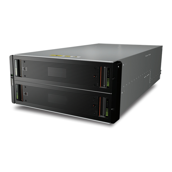
Chapter 2 System Overview 2.1 The OneStor SP-3584 The OneStor SP-3584 storage system is shown in Figure 2–1 Figure 2–2. It is housed in a 5U chassis containing two drawers of 42 drives each (84 drives in total). Figure 2–1... - Page 16 The system uses 3.5” or 2.5” SAS drives. 2.5” drives require a 3.5” adapter. Each drive is hot-pluggable and can be replaced on site. The OneStor SP-3584 is designed for high availability, with no single point of failure for data or power. The IT modules comply with the Storage Bridge Bay (SBB) v2.1 specification, which specifies interconnects, power budgets, power rails, mechanical and thermal form factors and footprints.
-
Page 17: The Enclosure Core Product
System Overview 2.2 The Enclosure Core Product The OneStor design concept is based on an enclosure subsystem together with a set of plug-in modules. A typical enclosure system (as supplied) comprises: • An enclosure chassis comprising: – Two sliding drawers containing Disk Drive In Carrier (DDIC) modules. –... -
Page 18: Enclosure Chassis
OneStor® SP-3584 Installation & User Guide Figure 2–3 Module Locations 2.3 Enclosure Chassis The chassis consists of a sheet metal enclosure assembly with an integrated midplane PCB, module runner system and two drawers for drive modules. The chassis has a 19 inch rack mounting that enables it to be installed on to standard 19 inch racks and uses 5 EIA units of rack space (8.75 inches;... -
Page 19: Drawers
System Overview 2.3.1 Drawers Each drawer contains 42 slots, each of which will accept a single DDIC containing a 3.5” drive or a 2.5” drive with an adapter. Opening a drawer does not interrupt the functioning of the system, and DDICs can be hot-swapped while the enclosure continues to operate. -
Page 20: Disk Drives In Carriers (Ddics)
OneStor® SP-3584 Installation & User Guide 2.3.2 Disk Drives in Carriers (DDICs) Each drive is housed in a carrier (see Figure 2–5) that enables secure insertion of the drive into the drawer and contains the appropriate SAS carrier transition card. Figure 2–5 A Disk Drive In Carrier (DDIC) The following hard disk drives are supported:... -
Page 21: Operator's Panel
System Overview Note The SP-3584 enclosure is not compatible with DDICs intended for the previous generation SP-2584 enclosure. A keying mechanism will prevent insertion. 2.3.3 Operator’s Panel The front of the enclosure features an operator’s (ops) panel (shown in Figure 2–6) on the left-hand side which contains the following: •... - Page 22 OneStor® SP-3584 Installation & User Guide 2.3.3.2 Input Switch Used to set the unit identification display (see section 4.4.1, “How To Set the Unit Identification Number”, on page 31). 2.3.3.3 Power On/Standby LED (Green/Amber) Shows amber when the system is in standby (not operational). Shows green when the system is on (operational).
-
Page 23: Power Supply Unit (Psu)
System Overview 2.4 Power Supply Unit (PSU) Power is provided by two 2214W PSUs, as shown in Figure 2–7. These require an input of 200 to 240VAC at 50 to 60Hz. Figure 2–7 2214W PSU Dual PSUs provide redundant power for the system: if one PSU fails, the other will keep the system running while you replace the faulty module. -
Page 24: Cooling Module
OneStor® SP-3584 Installation & User Guide Figure 2–8 PSU LEDs 2.5 Cooling Module The five cooling modules at the rear of the enclosure maintain all system components below their maximum temperature, assuming the ambient temperature is below 35°C. The speed of the fans in the cooling modules is controlled by the SBB I/O modules. Section 2.5.1, “System Airflow”, on page 17 describes the system airflow. -
Page 25: System Airflow
System Overview Figure 2–9 Cooling Module 2.5.1 System Airflow The system must be operated with low pressure rear exhaust installation. Back pressure created by the rack doors and obstacles is not to exceed 5 pascals (0.5mm water gauge). The cooling system provides sufficient capacity to ensure that maximum temperatures are not exceeded. -
Page 26: Enclosure Management
OneStor® SP-3584 Installation & User Guide Figure 2–10 12Gb/s SAS EBOD Module (other I/O modules are available) The system can operate with one or two modules. If the enclosure is run with a single module, the other I/O module bay must be filled with a blank module. The presence of I/O modules is checked when the power is switched on. -
Page 27: Installation
Chapter 3 Installation 3.1 Preparation Important Before attempting to install the system, read the safety chapter starting on page Important The enclosure must be mounted in a rack before use. Important Only service personnel should install the system. 3.1.1 ESD Precautions It is recommended that you fit and check a suitable anti-static wrist or ankle strap and observe all conventional ESD precautions when handling plug-in modules and components. -
Page 28: Unpacking The System
OneStor® SP-3584 Installation & User Guide 3.1.3 Unpacking the System Position the shipping case within 2m (6 feet) of the site where you intend to use your storage system. Inspect the packaging for crushes, cuts, water damage or any other evidence of mishandling during transit. -
Page 29: Installation
Installation 3.2 Installation 3.2.1 Installing the Rail Kit Caution An unpopulated enclosure can weigh up to 46kg (101lb). Do not try to lift it by yourself. Due to the weight of the enclosure, install it without the drive carriers. The adjustment range of the rail kit, from the inside of the front post to the inside of the rear post is 713mm to 884mm. - Page 30 OneStor® SP-3584 Installation & User Guide Figure 3–2 Mounting the System into a Rack (left hand rail only shown for clarity) Fully tighten all clamping screws and middle slide locking screws. Ensure the rear spacer clips (x4) are fitted tight to the edge of the rack post. Slide the enclosure fully home on its rails.
-
Page 31: Inserting Modules
Installation Figure 3–3 Rear Enclosure Mounting Caution Use only the power cords supplied or cords that match the specification in section B.5 on page Warning Once the enclosure is installed in the rack, dispose of the lifting straps. Due to the difficulty in attaching the straps once the enclosure is installed in the rack, the straps are not suitable for removing the enclosure from the rack. -
Page 32: Power Cord Connection
OneStor® SP-3584 Installation & User Guide 3.3 Power Cord Connection Important When more than one PSU is fitted, connect each PSU to separate and independent supplies to guarantee redundancy. Caution Always remove the power connections before you remove the PSU from the enclosure. 3.4 Grounding Checks The product must only be connected to a power source that has a safety electrical ground connection. - Page 33 Installation Figure 3–4 Valid Configuration...
- Page 34 OneStor® SP-3584 Installation & User Guide Important When connecting enclosures you must ensure that you do not create loops either within an I/O module (see Figure 3–5), or between I/O modules in the same enclosure (see Figure 3–6). You must also ensure that you do not create loops when connecting I/O modules on different enclosures (see Figure 3–7).
-
Page 35: Data Security
Installation Figure 3–7 Invalid Configuration: Loops Created Between Enclosures 3.6 Data Security • Power down your host computer and all attached peripheral devices before beginning installation. • Each enclosure contains up to 84 removable disk drive modules. Disk drives are fragile. Handle them with care, and keep them away from strong magnetic fields. - Page 36 OneStor® SP-3584 Installation & User Guide • If you remove a drive module, replace it immediately. If it is faulty, replace it with a drive module of the same type and capacity. • Ensure that all disk drives are removed from the enclosure before attempting to manhandle or move the rack installation.
-
Page 37: Operation
Chapter 4 Operation 4.1 Before You Begin Before you power up the enclosure make sure that all the modules are firmly seated in their correct bays. 4.2 Power On Caution Do not operate the enclosure system until the ambient temperature is within the specified operating range (see section A.5, “Temperature and Humidity”, on page 58). -
Page 38: Ops Panel Leds
OneStor® SP-3584 Installation & User Guide • Allow 15 seconds between turning the PSU off and back on again. • Allow 15 seconds between turning one PSU in the system on and the other PSU off. • Never turn off a PSU whilst any amber LED is lit on the partner PSU. •... -
Page 39: Unit Identification Number
Operation Figure 4–2 Ops Panel LEDs 4.4 Unit Identification Number 4.4.1 How To Set the Unit Identification Number The unit identification number is not set before the first system power on. The display is set to “00” (flashing). The enclosure continues to power up even if the unit identification number is not set. To set the unit identification number: Press and hold the Input switch on the ops panel for a period of five seconds. -
Page 40: Other Uses
OneStor® SP-3584 Installation & User Guide Once a unit identification number is set, it is stored in the midplane VPD by the Enclosure Management software and will appear when the enclosure is next powered on. In a situation where the VPD cannot be read, or where there is no enclosure management (no SBB I/O modules, or a single module with management failure) the enclosure will display “00”. -
Page 41: Troubleshooting
Chapter 5 Troubleshooting 5.1 Overview The OneStor SP-3584 enclosure system includes a Storage Enclosure Processor (SEP) and associated monitoring and control logic to enable it to diagnose problems within the enclosure’s power, cooling, PSU and drive systems. 5.2 Initial Start-Up Problems 5.2.1 Power Fault... -
Page 42: Leds
OneStor® SP-3584 Installation & User Guide Verify that the device driver for the operating system has been installed correctly. 5.3 LEDs LED colors are used consistently throughout the enclosure and its components for indicating status: • Green – good or positive indication. •... -
Page 43: Cooling Module Leds
Troubleshooting 5.3.2 Cooling Module LEDs Figure 5–2 Cooling Module LEDs Table 5–2 Cooling Module LED Descriptions Description Module OK Constant green indicates that the fan is working correctly. Off means the fan has failed. Follow the procedure in section 6.4, “Replacing a Cooling Module”, on page Fan Fault Amber indicates that a fan has failed. -
Page 44: Operator's Panel Leds
OneStor® SP-3584 Installation & User Guide 5.3.3 Operator’s Panel LEDs The operator’s (ops) panel (see Figure 5–3) displays the aggregated status of all the modules. Figure 5–3 Ops Panel LEDs Table 5–3 Ops Panel LED Descriptions Display/LED Description Unit Identification Display Usually shows the identification number for the enclosure, but can be used for other purposes. -
Page 45: Drawer Leds
Troubleshooting 5.3.4 Drawer LEDs Figure 5–4 Drawer LEDs Table 5–4 Drawer LED Descriptions Description Sideplane OK/Power Green if the sideplane card is working and there are no power problems. Good Drawer Fault Amber if a drawer component has failed. If it is a drive that has failed, an amber LED will be lit on the failed drive and you should follow the procedure in section 6.3, “Replacing a Disk Drive in Carrier (DDIC)”, on... -
Page 46: Disk Drive In Carrier (Ddic) Led
OneStor® SP-3584 Installation & User Guide 5.3.5 Disk Drive in Carrier (DDIC) LED Each disk drive has a single amber drive fault LED as shown in Figure 5–5. When lit, this indicates a drive failure – the drive should be replaced as soon as possible using the procedure described in section 6.3, “Replacing a Disk Drive in Carrier (DDIC)”, on page Figure 5–5 Drive Fault LED... -
Page 47: Sbb I/O Module Leds
Troubleshooting 5.3.6 SBB I/O Module LEDs The LEDs on the SBB I/O module will depend on the type of module in use. LEDs for a common I/O module (the 12Gb/s SAS EBOD) are shown in Figure 5–6 and described below. Figure 5–6 12Gb/s SAS EBOD I/O Module LEDs Table 5–5... -
Page 48: Thermal Sensors
Exceeding the limits of critical values will cause the Over-temperature alarm to occur (see Table 5–6.). 5.5 Troubleshooting The following sections describe problems that can occur with your OneStor SP-3584 and some possible solutions. For all of the problems listed in Table 5–6, the module fault LED on the ops panel (see Figure 2–6 on page... -
Page 49: Thermal Monitoring And Control
Troubleshooting 5.5.1 Thermal Monitoring and Control The OneStor enclosure system uses extensive thermal monitoring and takes a number of actions to ensure component temperatures are kept low and also to minimize acoustic noise. Air flow is from the front to the rear of the enclosure. Symptom Cause Action... -
Page 50: Dealing With Hardware Faults
OneStor® SP-3584 Installation & User Guide 5.6 Dealing with Hardware Faults Ensure that you have obtained a replacement module of the same type before removing any faulty module. Important If the enclosure is powered on and you remove a module, replace it immediately. If the system is used with any modules missing for more than a few seconds, the enclosure can begin to overheat, causing power failure and data loss. -
Page 51: Module Replacement
The drawer sideplanes can be hot-swapped in the field. Replacement of the sideplanes requires a special tool and should be carried out by service personnel only. Refer to the OneStor SP-3584 Hot Swap Side Card Quick Installation Guide for full instructions. -
Page 52: General Procedures
OneStor® SP-3584 Installation & User Guide 6.2 General Procedures 6.2.1 Opening a Drawer Make sure the anti-tamper locks are not engaged. The red arrows on the locks will point inwards if the locks are disengaged (see Figure 6–1). Unlock them if necessary by rotating them counterclockwise using a screwdriver with a torx T20 bit. -
Page 53: Closing A Drawer
Module Replacement Figure 6–2 Opening the Bottom Drawer Important The drawer must not be left open for more than two minutes while the enclosure is powered. 6.2.2 Closing a Drawer Press and hold both of the latches on the sides of the drawer (see Figure 6–3). -
Page 54: Replacing A Disk Drive In Carrier (Ddic)
OneStor® SP-3584 Installation & User Guide Figure 6–3 Drawer Latches 6.3 Replacing a Disk Drive in Carrier (DDIC) 6.3.1 Removing a DDIC Identify which drawer contains the drive to be replaced. If the drive number is known, the plan in Figure 6–4 can be used. - Page 55 Module Replacement Figure 6–4 Drive Location Plan Open the relevant drawer using the instructions in section 6.2.1, “Opening a Drawer”, on page Locate the drive to be replaced, either by using the drive plan (see Figure 6–4) or by looking for the amber LED on the drive that indicates a fault.
-
Page 56: Inserting A Ddic
OneStor® SP-3584 Installation & User Guide 6.3.2 Inserting a DDIC Important Failed drives must be replaced with approved drives. Contact your storage vendor for details. If the relevant drawer is not already open, open it using the instructions in section 6.2.1, “Opening a Drawer”, on page Lower the DDIC into the slot, with the drive capacity label facing towards you, as shown in... -
Page 57: Replacing A Cooling Module
Module Replacement Figure 6–7 Latch Position of a Correctly Inserted Drive Close the drawer using the instructions in section 6.2.2, “Closing a Drawer”, on page The drawers must be populated with drives in whole rows at a time (there are 3 rows of 14 drives per Note drawer). - Page 58 OneStor® SP-3584 Installation & User Guide Figure 6–8 Cooling Module LEDs As shown in Figure 6–9 Figure 6–10, push down and hold the black release latch (1) and pull the module out by its handle (2). Figure 6–9 Removing a Cooling Module (1)
-
Page 59: Inserting A Cooling Module
Module Replacement Figure 6–10 Removing a Cooling Module (2) Important The cooling module bay must not be empty for more than two minutes while the enclosure is powered. 6.4.2 Inserting a Cooling Module Rotate the cooling module so that the black release latch and handle are on the right-hand side. Slide the cooling module into its slot until the latch clicks home. -
Page 60: Inserting A Psu
OneStor® SP-3584 Installation & User Guide Figure 6–11 Removing a PSU Module (1) Figure 6–12 Removing a PSU Module (2) Important The PSU module bay must not be empty for more than two minutes while the enclosure is powered. 6.5.2 Inserting a PSU Rotate the PSU so that the red release latch and handle are on the left-hand side. -
Page 61: Replacing An Sbb I/O Module
Module Replacement Slide the PSU into its slot until the latch clicks home. The enclosure will automatically detect the new unit. 6.6 Replacing an SBB I/O Module Important Before removing an SBB I/O module, make sure you have a replacement module to insert. A variety of I/O modules can be used in the enclosure. - Page 62 OneStor® SP-3584 Installation & User Guide Figure 6–14 Removing an I/O Module (1) Figure 6–15 Removing an I/O Module (2) Important The SBB I/O module bay must not be empty for more than two minutes while the enclosure is powered.
-
Page 63: Inserting An Sbb I/O Module
Module Replacement 6.6.2 Inserting an SBB I/O Module Rotate the SBB I/O module so that the release latch is at the bottom. Open the release latch and rotate it to its most open position (as shown in Figure 6–15). Slide the I/O module into its slot until it will go no further and the handle has started to close. Close the latch until it clicks home. - Page 64 OneStor® SP-3584 Installation & User Guide...
-
Page 65: A Technical Specifications
Appendix A Technical Specifications Appendix A A.1 Dimensions Table A–1 Enclosure Dimensions Millimeters Inches Height (enclosure, overall) 222.3 8.75 Width across mounting flange 482.6 Depth from rear of front flanges to rear extremity of chassis A.2 Weights All weights are approximate. Kilograms Pounds Fully populated enclosure... -
Page 66: Components (Fully Populated)
OneStor® SP-3584 Installation & User Guide A.3 Components (Fully Populated) Drawers Disk Drives In Carriers (DDICs) 84 SBB I/O modules PSUs Cooling modules A.4 Thermal Thermal sensors 2 per sideplane (2 sideplanes per drawer) 2 per drawer baseplane (front) 1 per drawer baseplane (middle/rear) 2 per power supply Number in SBB I/O module is dependent on module type Airflow with all fans running... -
Page 67: Sbb I/O Modules
3.5”6 or 12Gb/s SAS solid state drive 2.5” 6 or 12Gb/s SAS solid state drive with 3.5” adapter All Drives Contact your storage vendor for details of other hard disk drives that are available for use in the OneStor SP-3584 storage system. -
Page 68: Shock And Vibration Tolerance
OneStor® SP-3584 Installation & User Guide A.10 Shock and Vibration Tolerance Operational vibration 0.21g RMS, 5 to 500Hz random with <10% throughput loss Operational shock 5g 10ms ½sine Relocation vibration (non- 0.3g, 2 to 200 to 2Hz swept sine operational) Non-operational vibration 1.04g RMS, 2 to 200Hz random Non-operational shock... -
Page 69: B Standards And Regulations
Appendix B Standards and Regulations Appendix B The OneStor SP-3584 is designed to comply with the standards and regulations enumerated in sections below. This includes any sample units. B.1 EMC Qualification OneStor SP-3584 carries EMC approval for the following territories: •... -
Page 70: Harmonics
EN 60950-1, and includes the national differences for all countries in the CB scheme. CCC applies to power and cooling modules only as FRUs. The OneStor SP-3584 enclosure meets the fire enclosure standards set out in the latest applicable edition of the UL 60950-1. B.3 Environmental and Recycling B.3.1 RoHS and JIG A... -
Page 71: Weee
Standards and Regulations Additionally, OneStor SP-3584 does not contain any substances or materials listed in Annex A of Joint Industry Guide JIG-101, Material Composition Declaration for Electronic Products (also known as 'JIG A Materials'). B.3.2 WEEE At the end of the product’s life, all scrap and waste electrical and electronic equipment should be recycled in accordance with national regulations applicable to the handling of hazardous or toxic electrical and electronic materials. -
Page 72: China Rohs
B.3.4 China RoHS OneStor SP-3584 complies with the Phase II China RoHS requirements for self-declaration and labeling. Seagate intends that OneStor SP-3584 shall be compliant with the Phase II China RoHS requirements for testing and certification when these are finalized. -
Page 73: Eup Directive
Standards and Regulations B.3.5 EuP Directive OneStor SP-3584 is not yet required to comply with the Environmentally Friendly Design of Energy Using Products (EuP) directive. This directive aims to reduce the amount of energy used during the whole of the product lifecycle: manufacture, use and end of life. -
Page 74: Potential For Radio Frequency Interference
OneStor® SP-3584 Installation & User Guide B.6 Potential for Radio Frequency Interference USA Federal Communications Commission (FCC) This equipment has been tested and found to comply with the limits for a class A digital device, pursuant Note to Part 15 of the FCC rules. These limits are designed to provide reasonable protection against harmful interference when the equipment is operated in a commercial environment. -
Page 75: C Glossary
Appendix C Glossary Appendix C Baseplane One of three PCBs in the drawer, parallel to the front bezel, that provide connections for the DDICs. DDIC Disk Drive In Carrier. GEM Generic Enclosure Management – the software that controls all programmable components in the enclosure. - Page 76 OneStor® SP-3584 Installation & User Guide...
-
Page 77: D Index
Index Index Appendix D numerics Host Bus Adapter 24 19 inch Rack mounting features 10 5U84 enclosure 24 I/O Module 9, 14, 16 Initial Start-up Problems 33 Input Switch 14 Alarm Conditions 40 Alarm Interpretation 40 anti-static wrist or ankle strap 5, 19, 43 LED 34 LED, PSU 34 Logical Status LED 14... - Page 78 OneStor® SP-3584 Installation & User Guide System Configurations 24 System Power On/Standby LED 14 Thermal Alarm 41 Thermal Monitoring and Control 41 Troubleshooting 40 Unit Identification Display 13 Visible and Audible Alarms 13 VPD 13...
Need help?
Do you have a question about the OneStor SP-3584 and is the answer not in the manual?
Questions and answers