Table of Contents
Advertisement
Quick Links
Advertisement
Chapters
Table of Contents
Troubleshooting

Subscribe to Our Youtube Channel
Related Manuals for Manitowoc 1400A


Summary of Contents for Manitowoc 1400A
- Page 1 National Crane 1400A Service Manual...
- Page 2 WARNING California Proposition 65 Breathing diesel engine exhaust exposes you to chemicals known to the State of California to cause cancer and birth defects or other reproductive harm. • Always start and operate the engine in a well-ventilated area. • If in an enclosed area, vent the exhaust to the outside.
- Page 3 SERVICE MANUAL This Manual has been prepared for and is considered part of - 1400A This Manual is Divided into the following Sections: SECTION 1 INTRODUCTION SECTION 2 HYDRAULIC SYSTEM SECTION 3 ELECTRIC SYSTEM SECTION 4 BOOM MAINTENANCE SECTION 5...
-
Page 5: Table Of Contents
Table of Contents SECTION 1 ..........Introduction General . - Page 6 Specifications 1400A ........
-
Page 7: Section 1
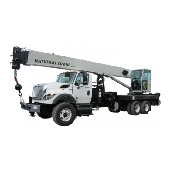
With proper care, This manual has been compiled to assist you in properly years of trouble-free service can be expected. operating and maintaining your Model 1400A Series National Crane reserves the right to make specification and National Crane (Figure 1-1). -
Page 8: Basic Nomenclature
INTRODUCTION SERVICE MANUAL 1400A Basic Nomenclature The nomenclature used to describe parts of a National Crane are described in Figure 1-2. This nomenclature is used throughout this manual. FIGURE 1-1 1-21-2019 Control # 104-07... - Page 9 1400A SERVICE MANUAL INTRODUCTION FIGURE 1-2 Item Component Item Component Hoist Cable, Wire Rope Crane Cab Crane Cab console Turret Operator’s Seat Stabilizer Front Outrigger (SFO), Front Outrigger Jack Boom Hydraulic Tank Boom Nose Hydraulic Pump Boom Rest Hydraulic Remote Controller (HRC)
-
Page 10: General Maintenance
INTRODUCTION SERVICE MANUAL 1400A GENERAL MAINTENANCE All supporting members (chains and cables) need to be parallel to each other and as near perpendicular as possible The suggestions listed below are helpful in analyzing and to the top of the object being lifted. -
Page 11: Bearings
1400A SERVICE MANUAL INTRODUCTION Bearings driver or a bar with a smooth flat end. If a sleeve bearing has an oil hole, align it with the oil hole in the mating part. Antifriction Bearings Gaskets When an antifriction bearing is removed, cover it to keep out dirt and abrasives. -
Page 12: Electrical
INTRODUCTION SERVICE MANUAL 1400A Keep The System Clean Remove the batteries If the machine is not used for an extended period of time. Store the batteries in a warm, dry When removing components of a hydraulic system, cover all place, preferably on wooden shelves. Never store on openings on both the component and the crane. -
Page 13: Fatigue Of Welded Structures
1400A SERVICE MANUAL INTRODUCTION Fatigue of Welded Structures Application of Medium Strength Loctite® NOTE: The fastener may be re-used; the adhesive may be Experience has shown that highly stressed welded re-applied over cured adhesive residue. structures when repeatedly subjected to varying stresses... - Page 14 INTRODUCTION SERVICE MANUAL 1400A Identification of fastener class is always necessary. When Torque wrenches are precision instruments and must be marked as a high strength bolt (class 5, 8, etc.), the handled with care. To ensure accuracy, calibrations must be mechanic must be aware that he/she is working with a highly made on a scheduled basis.
- Page 15 1400A SERVICE MANUAL INTRODUCTION Table 1-1 Inch Series with Coarse Threads (UNC) – Zinc Flake Coated Nominal Size, Threads per Torque (ft/lb) Inch, and Series Grade Maximum Nominal Minimum Designation 1/4-20 UNC 13.5 13.2 12.8 5/16-18 UNC 19.1 18.6 18.1 24.0...
- Page 16 INTRODUCTION SERVICE MANUAL 1400A Table 1-2 Inch Series with Fine Threads (UNF) – Zinc Flake Coated (Continued) Nominal Size, Threads per Torque (ft/lb) Inch, and Series Grade Maximum Nominal Minimum Designation 15.0 14.6 14.2 5/16-24 UNF 21.1 20.6 20.1 27.2 26.5...
- Page 17 1400A SERVICE MANUAL INTRODUCTION Table 1-3 Metric Series with Coarse Threads – Zinc Flake Coated (Continued) Torque (Nm) Nominal Size, Threads per Property Inch, and Series Class Maximum Nominal Minimum Designation M6x1.0 10.9 12.2 11.9 11.6 12.9 14.3 13.9 13.6 20.2...
- Page 18 INTRODUCTION SERVICE MANUAL 1400A Table 1-3 Metric Series with Coarse Threads – Zinc Flake Coated (Continued) Nominal Size, Threads per Torque (Nm) Property Inch, and Series Class Maximum Nominal Minimum Designation 2089.8 2037.6 1985.3 M36x4 10.9 2976.4 2902.0 2827.6 12.9 3483.0...
- Page 19 1400A SERVICE MANUAL INTRODUCTION Table 1-4 Metric Series with Fine Threads – Zinc Flake Coated (Continued) Nominal Size, Threads per Torque (Nm) Property Inch, and Series Class Maximum Nominal Minimum Designation 405.7 395.5 385.4 M20x1 10.9 577.8 563.3 548.9 12.9 676.1...
- Page 20 INTRODUCTION SERVICE MANUAL 1400A Table 1-5 Metric Series Screws of STAINLESS STEEL A2-70/A4-70 with Coarse Threads (Continued) Size Torque (Nm) M8x1.25 M10x1.5 Torque Values for fasteners with lubrication these torque values result in an 80% utilization of the yield strength.
- Page 21 1400A SERVICE MANUAL INTRODUCTION Inch Series with Coarse Threads (UNC) – Untreated (black finish) Table 1-9 Torque (ft/lb) Size Grade Maximum Nominal Minimum 1/4-20 12.5 11.5 5/16-18 3/8-16 7/16-14 1/2-13 9/16-12 5/8-11 259.5 3/4-10 7/8-9 1 1/8-7 1342 1288 1234...
- Page 22 INTRODUCTION SERVICE MANUAL 1400A Table 1-10 Inch Series with Fine Threads (UNF) – Untreated (black finish) (Continued) Torque (ft/lb) Size Grade Maximum Nominal Minimum 5/16-24 3/8-24 7/16-20 84.5 1/2-20 9/16-18 174.5 5/8-18 299.5 3/4-16 439.5 7/8-14 1-12 1009 644.5 1-14 908.5...
- Page 23 1400A SERVICE MANUAL INTRODUCTION Table 1-11 Metric Series with Coarse Threads – Untreated (black finish) (Continued) Torque (Nm) Property Size Class Maximum Nominal Minimum M5x0.8 10.9 12.9 10.5 10.5 M6x1 10.9 12.9 M8x1.25 10.9 36.5 12.9 43.5 M10x1.5 10.9 12.9 M12x1.75...
- Page 24 INTRODUCTION SERVICE MANUAL 1400A Table 1-11 Metric Series with Coarse Threads – Untreated (black finish) (Continued) Torque (Nm) Property Size Class Maximum Nominal Minimum 1538 1479 1420 M30x3.5 10.9 2163 2080 1997 12.9 2595 2495 2395 2681 2578.5 2476 M36x4 10.9...
-
Page 25: Weld Studs
1400A SERVICE MANUAL INTRODUCTION Table 1-12Metric Series with Fine Threads – Untreated (black finish) (Continued) Torque (Nm) Property Size Class Maximum Nominal Minimum 331.5 M18x1.5 10.9 12.9 M20X1 10.9 667.5 12.9 464.5 M20x1.5 10.9 12.9 M22x1.5 10.9 888.5 12.9 1111... -
Page 26: Torque Wrenches
INTRODUCTION SERVICE MANUAL 1400A received residual oils. Special lubricants are not recommended. Torque values for bolts listed above are not affected with the use of Loctite. Loctite should not be used on rotation bearing fasteners. Hardened washers should be used with... -
Page 27: Wire Rope
1400A SERVICE MANUAL INTRODUCTION Ta x L Ta x L TW = L + A L - A = Length of torque wrench in inches (center of drive Ta = Torque required (specified) tang to handle pivot pin or center of hand grip... -
Page 28: Recommendations For Servicing Wire Rope
Manitowoc CraneCARE. Do not build lengths from • reduction of rope diameter below nominal diameter. -
Page 29: Wire Rope Replacement (All Wire Rope)
Consensus Standard as referenced by Federal Government end of the annealed wire at right angles to the wire and wrap Agencies and Manitowoc CraneCARE recommendations to it tightly over the portion in the groove. help determine when wire rope needs to be replaced. Wire... - Page 30 INTRODUCTION SERVICE MANUAL 1400A Method 2 NOTE: Non-preformed wire rope should have two seizings located on each side of the cut (Figure 1-8). Wind a length of soft annealed wire around the wire rope at least seven times. Twist the two ends together in the center of the seizing.
-
Page 31: Section 2
1400A SERVICE MANUAL HYDRAULIC SYSTEM SECTION 2 HYDRAULIC SYSTEM SECTION CONTENTS Maintenance ......2-4 Telescope In and Telescope Out Reliefs. - Page 32 HYDRAULIC SYSTEM SERVICE MANUAL 1400A Description Symbol Description Symbol Hydraulic Reservoir - Stores, cools, and Filter - Removes contamination from cleans machines hydraulic fluid supply. hydraulic fluid. Hydraulic Return Lines - Terminated at (1) Filter with Bypass Valve - Bypass valve below fluid level (2) above fluid level.
- Page 33 1400A SERVICE MANUAL HYDRAULIC SYSTEM Description Symbol Description Symbol Single Acting Cylinder - Extended Manually Operated - Valve shifted hydraulically and retracted with a spring. manually with check to allow flow back to tank. Double Acting Cylinder - Extended and retracted hydraulically.
-
Page 34: Parts Replacement
HYDRAULIC SYSTEM SERVICE MANUAL 1400A MAINTENANCE the machine or another hose and has a minimum of bending and twisting. Tighten bolts in both couplings. General Due to manufacturing methods, there is a natural curvature to a hydraulic hose. The hose should be installed so any Before adjustments and repairs are started on a crane, the bend is with this curvature. -
Page 35: Removing Air From The Hydraulic System
1400A SERVICE MANUAL HYDRAULIC SYSTEM Remove the reservoir drain plug. Allow about three 15. Disconnect the return line from the hoist motor and fully minutes after hydraulic oil stops flowing from the drain hoist up. port for the side walls to drain. -
Page 36: System Description
The hydraulic system is pressure compensated with a closed The RCL dump manifold is located in the turret and disables center. The hydraulic system of the 1400A consist of the crane functions when the RCL senses an impending tipping following: condition. -
Page 37: Valves
1400A SERVICE MANUAL HYDRAULIC SYSTEM Hydraulic Remote Controllers Front Outrigger Manifold The front outrigger manifold is located in the center of the The crane functions are controlled by hydraulic remote front manifold and controls the extend and retract circuits for controllers (HRC) on the armrest of the operators seat. - Page 38 HYDRAULIC SYSTEM SERVICE MANUAL 1400A Item Component Item Component Rear Outrigger Solenoid Manifold Main Control Valve (lift, telescope, hoist) Front Outrigger Solenoid Manifold Main Control Valve (Optional Aux Hoist) Outrigger Pressure Reducing Valve Swing Control Valve Swing Speed Control Valve...
-
Page 39: Pressure Setting Procedures
1400A SERVICE MANUAL HYDRAULIC SYSTEM FIGURE 2-2 Boom Up Relief Telescope Out Relief Main Control Valve with Optional Aux Hoist Section Load Sense Relief System Relief Telescope In Relief Boom Down Relief PRESSURE SETTING PROCEDURES pressure setting has been attained, tighten the... -
Page 40: Relief Valve Setting Procedures
HYDRAULIC SYSTEM SERVICE MANUAL 1400A Pressure Setting Valve To Be Set Tolerance kPa (PSI) Adjustment Location kPa (PSI) Telescope Retract Relief 15,513 (2,250) ±689 kPa (100 psi) Main Control Valve Telescope Extend Relief 18,615 (2,700) ±689 kPa (100 psi) Main Control Valve Hydraulic Remote Controller Load Sense Pilot 23,442 (3,400) ±689 kPa (100 psi) -
Page 41: Telescope In And Telescope Out Reliefs
1400A SERVICE MANUAL HYDRAULIC SYSTEM Telescope In and Telescope Out Reliefs FIGURE 2-4 Outrigger Telescope Cylinder Work Port Hoses Stabilizer Down Beam Out Beam In Stabilizer UP FIGURE 2-5 Remove the extend and retract (work port) hoses from the telescope cylinder (Figure 2-4). Cap the telescope Start engine and set throttle to governed rpm. -
Page 42: Single Front Outrigger (Sfo)
HYDRAULIC SYSTEM SERVICE MANUAL 1400A Single Front Outrigger (SFO) Adjust the extend relief valve on the front outrigger port block to 3447+689/-0 kPa (500 psi +100/-0). Disconnect extend retract lines Shut down the engine. (Figure 2-7). Cap the retract line and install a gauge in the extend line. -
Page 43: Hydraulic Reservoir And Filter
1400A SERVICE MANUAL HYDRAULIC SYSTEM Hydraulic Reservoir and Filter A filler cap on the top of the reservoir is for filling the reservoir. The filler cap includes a strainer for catching The reservoir, (Figure 2-8) is attached to the front of the truck contaminants and gaskets to prevent leaking. -
Page 44: Hydraulic Filter Replacement
HYDRAULIC SYSTEM SERVICE MANUAL 1400A Hydraulic Filter Replacement energizes the fan relay when the oil temperature reaches 49 °C (120°F). The filter is mounted in the oil reservoir, and is a replaceable element type. NOTE: If the temperature sensor in the cooling core fails, The filter requires a 5 Micron replacement element. -
Page 45: Hydraulic Valves
1400A SERVICE MANUAL HYDRAULIC SYSTEM Hydraulic Valves true center position. Excessive system pressure can create both internal and external leaks in valves that are otherwise Directional Control Valve sound. Only qualified technicians using the correct equipment should make pressure adjustments when The main control valve controls the hoist, lift cylinder, and pressure adjustments are needed. -
Page 46: Hydraulic Pump
HYDRAULIC SYSTEM SERVICE MANUAL 1400A brake switch located on the front console and is used to activate the swing brake and park the turret in position. Press the switch to activate the swing brake to keep the turret from rotating. A red LED is illuminated when the swing brake Hydraulic Remote switch is applied. -
Page 47: Initial Pump Installation
1400A SERVICE MANUAL HYDRAULIC SYSTEM Position the pump so that hydraulic lines can be connected without sharp bends especially the large Pump Mounting Flange suction line from the reservoir. For drive line installation, install the pump mount to the truck frame. -
Page 48: Pump Margin Pressure Setting
HYDRAULIC SYSTEM SERVICE MANUAL 1400A Start the engine and engage the PTO while monitoring 11. Check/adjust pump margin pressure; see “Pump Margin the pressure gauge. Do not operate any hydraulic Pressure Setting” on page 18. levers. If the pump does not build up pressure to 13 to 12. - Page 49 1400A SERVICE MANUAL HYDRAULIC SYSTEM 7715 FIGURE 2-12 7590 FIGURE 2-13 National Crane 2-19 1-21-2019 Control # 104-07...
-
Page 50: Trouble Diagnosis
1 7/8-12 (37.82) (43.69) NOTE: Contact your National Crane Distributor or Manitowoc Crane Care for O-Ring boss seal kits. TROUBLE DIAGNOSIS possible solution. These are not all inclusive but are designed to help isolate the problem and should be checked... - Page 51 1400A SERVICE MANUAL HYDRAULIC SYSTEM CONDITION POSSIBLE CAUSE POSSIBLE SOLUTION Low hydraulic oil level. Fill reservoir. If the temperature is too high, check the cooler Hydraulic oil temperature too high (thin oil) Slow response. circuit. If the temperature is too low, warm up or too low (thick oil).
- Page 52 HYDRAULIC SYSTEM SERVICE MANUAL 1400A CONDITION POSSIBLE CAUSE POSSIBLE SOLUTION Pilot pressure at valve bonnets should be 0.7 to 2.4 Valve spools not fully open. MPa (100 to 350 PSI) so valve has full throw. Plugged diffuser Remove from tank and clean.
- Page 53 1400A SERVICE MANUAL HYDRAULIC SYSTEM CONDITION POSSIBLE CAUSE POSSIBLE SOLUTION Low oil temperature. Allow unit to warm up. Low hydraulic oil supply. Check and fill with crane in travel position. Suction line kinked, collapsed or blocked. Clear blockage. Hydraulic oil too thick.
- Page 54 HYDRAULIC SYSTEM SERVICE MANUAL 1400A CONDITION POSSIBLE CAUSE POSSIBLE SOLUTION Cables not attached correctly. Reconnect, replace and/or adjust cables. Anti-two block system shut down. Lower hook, and extend load. Defective anti-two block system. Check anti-two block system; repair if defective.
-
Page 55: Section 3
1400A SERVICE MANUAL ELECTRIC SYSTEM SECTION 3 ELECTRIC SYSTEM SECTION CONTENTS Description ....... 3-1 Micro Relay Fuse Block . -
Page 56: General Troubleshooting
ELECTRIC SYSTEM SERVICE MANUAL 1400A improper mounting, foreign material between the brushes and slip rings, worn brushes, improper spring tension on the DANGER brush assembly, and loose setscrews on the slip ring assembly. Refer to the electrical schematic and wiring Remove all rings, watches, and other jewelry before diagram for slip ring connections and amperages. - Page 57 1400A SERVICE MANUAL ELECTRIC SYSTEM Crane Cab Console Item Component Crane cab heater fuse holder (F1) (20A) (red leads) Crane power fuse holder (F1) (30A) Cab accessory fuse holder (F2) (20A) (orange leads) Main power relay Seat safety switch fuse holder (F3) (3A)
-
Page 58: Individual Fuse Holders
ELECTRIC SYSTEM SERVICE MANUAL 1400A INDIVIDUAL FUSE HOLDERS The side panel (13) may need to be removed to gain access to the individual fuse holders. There are several fuses contained in individual fuse holders located in the crane cab console (Figure 3-1). These are: RELAY FUSE BLOCKS •... -
Page 59: Mini Relay Fuse Block
1400A SERVICE MANUAL ELECTRIC SYSTEM Mini Relay Fuse Block FIGURE 3-3 Mini Relay Fuse Block • F9 - RCL dump valve solenoid circuit. • F10 - Switch LED’s on the crane cab console. The mini relay fuse block is located on the right and contains... -
Page 60: Vec Module
ELECTRIC SYSTEM SERVICE MANUAL 1400A Item Relay Truck Ignition Oil Cooler Throttle Control Engine Start Not Used Crane Ignition Outrigger Control Throttle Control - Radio Remote 8129 FIGURE 3-4 VEC MODULE disables this relay when the truck is started with the radio remote. -
Page 61: Rcl, Atb, And Crane Manifold Solenoids
1400A SERVICE MANUAL ELECTRIC SYSTEM RCL and ATB dump solenoids Item Relay Boom Down Auxiliary Hoist Up (optional) Crane Boom Telescope Extend Manifold Solenoids Hoist Up Crane Function Power Air Conditioner (Optional) Swing Brake FIGURE 3-5 RCL, ATB, and Crane Manifold Solenoids Before replacing a solenoid, check the connector for corrosion. -
Page 62: Outrigger Manifolds
ELECTRIC SYSTEM SERVICE MANUAL 1400A OUTRIGGER MANIFOLDS The swing and outrigger functions are on the same hydraulic There are two outrigger manifolds located on the carrier circuit however, only one function at a time can be working. frame. The front outrigger manifold is mounted on the center... -
Page 63: Hydraulic Oil Cooler
1400A SERVICE MANUAL ELECTRIC SYSTEM NOTE: Solenoid as viewed from the rear of the truck. Item Solenoid Passenger Side Stabilizer Passenger Side Beam Driver Side Beam FIGURE 3-7 Driver Side Stabilizer HYDRAULIC OIL COOLER Not all return flow is routed through the oil cooler. A check valve 206 kPa (30 psi) limits the flow through the cooler. - Page 64 ELECTRIC SYSTEM SERVICE MANUAL 1400A THIS PAGE BLANK 3-10 1-21-2019 Control # 104-07...
-
Page 65: Four Section Boom
1400A SERVICE MANUAL BOOM MAINTENANCE SECTION 4 BOOM MAINTENANCE SECTION CONTENTS Four Section boom ......4-1 Top/Rear Wear Pad Adjustment . -
Page 66: Boom Removal
BOOM MAINTENANCE SERVICE MANUAL 1400A Proportioning Cable Section Section Section Section Boom Nose Retract Cables for the 4 Section Extend Cables for the 4 Section Retract Cables for the 3 Section FIGURE 4-1 BOOM REMOVAL BOOM DISASSEMBLY Extend and set machine outriggers. The boom must be The boom can be disassembled by using two different completely retracted and stowed in the boom rest. -
Page 67: Boom Disassembly Alternative #1
1400A SERVICE MANUAL BOOM MAINTENANCE Boom Disassembly Alternative #1 12. Remove the six capscrews securing the retract sheave pin and the retract sheaves to the 2 section. Remove NOTE: If wear pads and shims are removed, tag all shims the sheaves and pins. -
Page 68: Four Section Boom Assembly
BOOM MAINTENANCE SERVICE MANUAL 1400A Boom Disassembly Alternative #2 Inspect all sheaves for excessive groove wear or abnormal rim wear. Replace as required. The extend cylinder can be removed from the rear of the Inspect all sheave bearings for excessive wear or cut boom without disassembly of the boom sections. - Page 69 1400A SERVICE MANUAL BOOM MAINTENANCE Install the top rear wear pads and cam plates to the top 19. Install the cable guide and spacer to the top of the 2 of the 4 boom section. Install the capscrews through section.
- Page 70 BOOM MAINTENANCE SERVICE MANUAL 1400A 31. Visually verify that the extend cables are properly routed 40. Install the upper spacer to front of 1 section. on the sheaves and continue to slide with the extend 41. Install the front side wear pads with the appropriate cylinder and cables into the boom sections.
-
Page 71: Five Section Boom
1400A SERVICE MANUAL BOOM MAINTENANCE FIVE SECTION BOOM boom section extend cables are attached to the base of the section, reeved around sheaves at the tip of the 2 The five section boom is powered by a two-stage double- section, and attach to the base of the 3 section. -
Page 72: Five Section Boom Removal
BOOM MAINTENANCE SERVICE MANUAL 1400A NOTE: The extend cable sheaves located at the top front • Remove the front upper spacer bar from 1 section. of the 2 section can be accessed from any boom • Remove and tag the four side wear pads and shims length. - Page 73 1400A SERVICE MANUAL BOOM MAINTENANCE 14. Place the 3 assembly on a suitable horizontal • Pull the retract cables out and keep retract cables surface. Take care not to damage the retract cables taunt while pulling the 4 section assembly out while lifting or supporting the 3 assembly.
- Page 74 BOOM MAINTENANCE SERVICE MANUAL 1400A mm (0.015 inch) larger than pin diameter, bearing must be replaced. Any cut or gouge which causes the bearing Section Cable Thread liner to lose strands is cause for bearing replacement. Extend Cable Clean and inspect all cable assemblies according to wire Section rope inspection procedures in this section.
- Page 75 1400A SERVICE MANUAL BOOM MAINTENANCE 11. Install 4 section retract cable button end into anchor threaded end gets close to the grooves in the lower front point in 4 section. pad plate and adjust as necessary to allow proper placement. A scribe mark on the 4 section at full •...
- Page 76 BOOM MAINTENANCE SERVICE MANUAL 1400A 27. Install the cable anchor on the extend cables. Tighten 30. Lower extend cylinder to a position parallel with the the capscrews just enough to clamp the two halves of boom assembly and slowly push the cylinder...
- Page 77 1400A SERVICE MANUAL BOOM MAINTENANCE • Install the cable guide and wear pad to the top of the • Raise the 2 section and cylinder section. assembly high enough in 1 section to allow the plate with pads to slide between the sections.
-
Page 78: Top/Rear Wear Pad Adjustment
BOOM MAINTENANCE SERVICE MANUAL 1400A Wear Pad Inspection FIGURE 4-5 Inspect the top and bottom wear pads periodically for signs of abrasion or excessive wear. Excessive is defined as 4.8 mm (3/16 inch) less than the original pad thickness. Original... -
Page 79: Inner Side Pad Clearance
1400A SERVICE MANUAL BOOM MAINTENANCE Install the new pads with Teflon inserts on the plates or boom sections. Reassemble plates in boom in proper locations. Inner Side Pad Clearance 2 Plcs Top Outer Cylinder Section Anchor Bars 1 Plc Bottom... -
Page 80: Inner Side Pad Clearance Example
BOOM MAINTENANCE SERVICE MANUAL 1400A Inner Side Pad Clearance Example = 12.12 (307.8) as measured at the front = 12.06 (306.3) as measured at the back near the cylinder anchor bars = 10.86 (275.8) as measured at top front pad location = 10.94 (277.8) as measured at top back pad location... -
Page 81: Cable Tensioning
1400A SERVICE MANUAL BOOM MAINTENANCE A boom assembly is considered properly timed when When tightening/loosening the first (adjustment) nuts on telescoping sections extend equally relative to each other cables, secure cable using the wrench flats at the front of the and bottom out simultaneously at full retraction and do not cable ends to prevent cable twist. -
Page 82: Section Boom W/ 2 Stage Cylinder Cable Positioning
BOOM MAINTENANCE SERVICE MANUAL 1400A Four section boom with one stage cylinder. 432 retract cables. Cable tensioning to be in the following order: Three section boom with one stage cylinder. 123 extend cables. Cable tensioning to be in the following order: 321 retract cables. - Page 83 1400A SERVICE MANUAL BOOM MAINTENANCE 234 and 432 cable balancing 345 and 543 cable balancing Extension Extension Measure the extension gaps between the third and Measure the extension gaps between the fourth and fifth fourth section and the second and third section.
-
Page 84: 4- Section Boom W/ 2 Stage Cylinder Cable Positioning
BOOM MAINTENANCE SERVICE MANUAL 1400A 4- Section Boom w/ 2 Stage Cylinder Cable Positioning 1/2/3 EXTEND 2/3/4 EXTEND 1ST STAGE BASE 2ND STAGE 3RD STAGE 4th STAGE 8860-2 4/3/2 RETRACT 3/2/1 RETRACT FIGURE 7 Cable Tightening Sequence 4 Section Boom with Two... -
Page 85: 4- Section Boom W/ 1 Stage Cylinder Cable Positioning
1400A SERVICE MANUAL BOOM MAINTENANCE The fourth section should have moved out. Tighten the 432 retract cable located at the front bottom of the second section the difference in the retraction gap Tightening until the extension gap between the third and measurements. -
Page 86: Cable Retention
BOOM MAINTENANCE SERVICE MANUAL 1400A Tightening until the retraction gap between the first and Tightening until the extension gap between the third and second section and the retraction gap between the fourth section is equal to the extension gap between the second and the third are equal. - Page 87 1400A SERVICE MANUAL BOOM MAINTENANCE N u t c o n f i g u r a t i o n ( s e e F i g u r e 9 ) w i l l b e F i r s t N u t TORQUE VALUES for Second Nut: (ADJUSTMENT) and Second Nut (TORQUED).
- Page 88 BOOM MAINTENANCE SERVICE MANUAL 1400A THIS PAGE BLANK 4-24 1-21-2019 Control # 104-07...
-
Page 89: Section 5
Troubleshooting ......5-11 DESCRIPTION MAINTENANCE The 1400A hoist is composed of motor control valve, a Inspect the hoist daily for oil leaks, loose bolts, and worn hydraulic motor, a multiple disc brake, and a pair of planetary hoist cable. -
Page 90: Warm-Up Procedure
HOIST SERVICE MANUAL 1400A Item Component Item Component Alignment Ear Hoist Boom Brake U-bolt Motor Rope Mesh Guard Motor Control Valve Case Drain Mounting Bolts Brake Hydraulic Pressure Line Motor Hydraulic Pressure Line Hydraulic Return Line Alignment Slot FIGURE 5-1 Warm-up Procedure Remove the cable from the hoist drum. -
Page 91: Drum Rotation Indicator
1400A SERVICE MANUAL HOIST Hoist Installation Series “A” units can be distinguished by a single cable connection on the HMS, located on the left side of the hoist. Remove the rope mesh guard from hoist and attach a Series “B” units have a second connection (CAN J1939) lifting device to the hoist. -
Page 92: Programming The Minimum Wrap Indicator
HOIST SERVICE MANUAL 1400A Insert the DRI into the drum. Rotate the DRI (1, Run the hoist to the first set point, third wrap of wire or Figure 5-3) so that the DRI shaft (2) engages the drive synthetic rope. This deactivates the alarm output. -
Page 93: Troubleshooting
1400A SERVICE MANUAL HOIST To use Shipping Mode: Install the wire rope on the drum. Refer to the appropriate winch manual for more information. See See “Programming the Minimum Wrap Indicator” on page 5-4 to set the end points. Remove the programming button cover screw (1, Figure 5-5). -
Page 94: Reassembly
HOIST SERVICE MANUAL 1400A lockwashers (44) holding motor (12-4) to the brake 12. Inspect retaining ring (48) to insure it is still in groove cover (20). See Servicing The Motor section for motor and is not bent over. and counterbalance valve disassembly. -
Page 95: Hoist Service
1400A SERVICE MANUAL HOIST 17. Fill both the gearbox and the brake section with the by the removal tools and polish if necessary. Friction proper amount and type of lubricants. See Section 8 discs should measure no less than 0.055 in. thickness Lubrication. - Page 96 HOIST SERVICE MANUAL 1400A INPUT GEAR SET 36-5 36-1 36-4 36-3 36-7 36-6 36-2 36-7 7-10 OUTPUT GEAR SET 12-4 12-5 12-2 12-3 12-1 FIGURE 5-7 1-21-2019 Control # 104-07...
- Page 97 1400A SERVICE MANUAL HOIST Item Quantity Description Item Quantity Description Bushing Capscrew Friction Disc Support Rod Stator Plate Capscrew Brake Cover Output Gear Set Brake Housing Output Carrier Omit Omit Planet Gear Retaining Ring Planet Pin Brake Spring Retaining Ring...
-
Page 98: Planetary Set
HOIST SERVICE MANUAL 1400A 13. Install the stator plates (19) and friction discs (18) into 20. Check the brake release with a portable hydraulic pump. the brake housing starting with a stator and alternating Full release should be obtained at 250 psi, plus or minus friction discs and stator plates. -
Page 99: Troubleshooting
1400A SERVICE MANUAL HOIST TROUBLESHOOTING 12-3 Metering Hole 12-1 12-4 12-2 12-1 FIGURE 5-9 Problem Cause Solution Check the system for restrictions and reduce the Excessive back pressure in the system. back pressure. Hoist does not hold Brake discs are worn out. - Page 100 HOIST SERVICE MANUAL 1400A THIS PAGE BLANK 5-12 1-21-2019 Control # 104-07...
-
Page 101: Section 6
The purpose of the swing system is to allow the crane turret When the hydraulic remote control is positioned to select to rotate atop the carrier frame. The 1400A swing system right or left swing, the flow through the control valve is provides full 360 degree rotation in both directions and is directed to the swing motor. - Page 102 SWING SERVICE MANUAL 1400A Motor Control Valve Brake Coolant Out Brake Release Brake Brake Brake Apply Coolant In Oil Fill Gearbox Oil Drain FIGURE 6-1 1-21-2019 Control # 104-07...
- Page 103 1400A SERVICE MANUAL SWING Outer Planetary Gear Inner Planetary Gear FIGURE 6-2 Item Component Item Component Cap Screw (8) Housing Drain Plugs Output Shaft Plate Seal Retaining Washer Lower Bearing Output Planetary Pin Lower Bearing Race Washer Upper Bering Race...
-
Page 104: Swing Gearbox And Brake
SWING SERVICE MANUAL 1400A SWING GEARBOX AND BRAKE Disassembly The rotation drive is a double planetary gear reducer with an (See Figure 6-2 for reference (#) numbers.) integral brake. The gear reducer is designed to give long life With a scribe or small punch make a set of marks on the in heavy duty applications such as crane rotation. -
Page 105: Output Planetary Repair
1400A SERVICE MANUAL SWING Unit Assembly Slide planet gears (25) and races (28) out of the input carrier (13). (See Figure 6-2 for reference numbers.) Remove the plate (30) from the input carrier (13). Place the gear housing (1) on a table with the gear end If needle bearings (29) must be replaced, they may now of the output shaft (2) on the table surface. -
Page 106: Swing Brake
SWING SERVICE MANUAL 1400A 10. Install the thrust washer (11) and the output sun gear the dynamic brake piston which reapplies pressure to the (12) in the end of the output gear set (10). brake discs. 11. Lower the input gear set (13) into the gear housing (1) -
Page 107: Assembly
1400A SERVICE MANUAL SWING FIGURE 6-3 Item Component Item Component O-ring Stator Plates Housing Friction Discs Seal Backup Ring Bearing O-ring Backup Ring O-ring O-ring Backup Ring O-ring Park Brake Piston Backup Ring Springs Brake Piston O-ring Retaining Ring Cover... -
Page 108: Swing Bearing
SWING SERVICE MANUAL 1400A MAINTENANCE Gently slide the brake piston (10) into the brake housing. Press down on the piston with the heal of both hands to General squeeze the o-rings into the housing. Push the piston completely down into the housing. -
Page 109: Swing Bearing Bolts
1400A SERVICE MANUAL SWING Torque wrenches are precision instruments and must be All handles must be parallel to the step wrench during handled with care. To ensure accuracy, calibrations must be final tightening. Multiplier reaction bars may be made on a scheduled basis. Whenever there is a possibility... - Page 110 SWING SERVICE MANUAL 1400A 30 29 FIGURE 6-5 Inner Race Bolt FIGURE 6-6 6-10 1-21-2019 Control # 104-07...
-
Page 111: Bearing Clearance
1400A SERVICE MANUAL SWING Outer Race Torquing Set the dial indicator at zero. Raise the boom about 3 inches above the boom rest. The outer race bolts are located on top of the bearing (Figure 6-7). Record the deflection indicated on the dial. -
Page 112: Bearing Replacement
SWING SERVICE MANUAL 1400A FIGURE 6-9 BEARING REPLACEMENT Slowly rotate the boom back to 20° off front position. Elevate the boom slightly and shut down the engine. Removal Tag and disconnect the battery cables. Fully extend and set the outriggers enough to take up Remove the boom and lift cylinder following the the slack in the pads. -
Page 113: Installation
1400A SERVICE MANUAL SWING Using an appropriate lifting device, align the turret over the carrier same position that it was before removal. DANGER Carefully lower the turret into position on the bearing Ensure the lifting device is capable of supporting the plate. -
Page 114: Slew Potentiometer Adjustment
SWING SERVICE MANUAL 1400A Slew Potentiometer Electrical Swivel Cover FIGURE 6-11 Slew Potentiometer Adjustment Disengage the swing brake and swing approximately 10° to the left (counterclockwise). Slowly swing back to Rotate the turret over the front and set the swing brake. -
Page 115: Section 7
1400A SERVICE MANUAL OUTRIGGERS SECTION 7 OUTRIGGERS SECTION CONTENTS Description ....... 7-1 Cable Tensioning. - Page 116 OUTRIGGERS SERVICE MANUAL1400A Section Beam Section Beam Top Cable Adjustment Outrigger Lock Pin Extend Cylinder Anchor Bolts Stabilizer Bottom Cable Adjustment Outrigger Float FIGURE 7-1 Hydraulic LInes 1-21-2019 Control # 104-07...
-
Page 117: Removal
1400A SERVICE MANUAL OUTRIGGERS FIGURE 7-2 Extend/Retract Cables Top Cable Adjustment Trunnion Hydraulic Hoses Cable Sheaves on 2 Section Hydraulic Hose Reel on the Nose of the Extend Cylinder Anchor Brackets Hydraulic Tubes to Cable Sheaves on Stabilizer Cylinder the Nose of the... - Page 118 OUTRIGGERS SERVICE MANUAL1400A removed from 2 section because loose parts such as the hose sheaves can fall off the shaft and be damaged. 16. Place the cylinder on a suitable horizontal surface and remove the hoses, cable sheaves, hose reels, and shaft. 17.
-
Page 119: Cable Tensioning
1400A SERVICE MANUAL OUTRIGGERS Installation 19. Attach the cables, fittings, and hoses to cylinder butt plate. The cylinder length may need to be adjusted to NOTE: When assembling the outriggers do the following: allow assembly. • Always use the jam nuts and thread the first nut on 20. -
Page 120: Outrigger Monitoring System (Oms) (Optional-Standard In North America)
OUTRIGGERS SERVICE MANUAL1400A OUTRIGGER MONITORING SYSTEM (OMS) Remove (OPTIONAL—STANDARD IN NORTH Fully retract outrigger beam. AMERICA) Remove outrigger box cover (1, Figure 7-6). The Outrigger Monitoring System (OMS) aids the operator in Disconnect spring clip (2, Figure 7-6) from its attaching accurately programming the Rated Capacity Limiter (RCL) point on outrigger beam. -
Page 121: Section 8
Open Gear Lubricant ..... . 8-2 1400A Hydraulic Oil Reservoir Level ... 8-9 Antifreeze/Coolant (for Cab Heater) . -
Page 122: Lubricants
This is a special high-graphite adhesive lubricant that helps suitability of a specific fluid, check with your authorized to eliminate fretting corrosion, is water resistant, and forms a National Cranes distributor or Manitowoc Crane Care. dry lubrication film which does not attract dust. Lubricant NOTE: All fluids and lubricants may be purchased by meets NLGI Class 1-2 specifications. -
Page 123: Arctic Hydraulic Oil
Temperature Down to -9°C (15°F) to -29°C (-20°F) level and must meet John Deere Standard JDM J20C. Contact your National Crane distributor or Manitowoc Crane For colder operating conditions, the standard fluid may be Care if you have any questions. - Page 124 LUBRICATION SERVICE MANUAL 1400A When wear pads or rotation bearings are lubricated, cycle the components and lubricate again to ensure complete CAUTION lubrication of the entire wear area. Lubrication intervals are to be used only as a guide. Actual intervals should be formulated by the operator to...
- Page 125 1400A SERVICE MANUAL LUBRICATION Lubrication Chart Grease Tube FIGURE 8-2 Table 8-1 Recommended Item Application Procedure Frequency Lubricant Weekly As Required Hydraulic oil reservoir HYDO Check fill change Semi-Annually After first 40 Hrs. As indicated by Oil filter, Hydraulic oil reservoir Change or clean gauge thereafter.
-
Page 126: Internal Cable Sheave Lubrication
(National P/N 955045). in back of the boom, look up through the hoist mount at • Contact Manitowoc Crane Care to obtain this tip. the pins to determine the amount of grease. Lubrication of the extend and retract sheaves is as follows: Boom Lubrication Inner Wear Pad Recommended lubricant is EP-3MG grease. -
Page 127: Boom Lubrication Side/Bottom Wear Pads
1400A SERVICE MANUAL LUBRICATION Fully extend and set the outriggers. Apply grease at all contact points for the wear pads on Access Holes 2 Section Wear Pad the top of the 2 section through the access holes in the Access Holes 3 Section section with a grease gun (Figure 8-3). -
Page 128: Hoist Gearbox Oil Level Check
LUBRICATION SERVICE MANUAL 1400A DANGER Oil Fill Do not use EP type gear lubes in the brake section. This Remove the 1” fill pipe from the drain hole. may prevent proper operation and cause the load to fall Rotate the drum until the drain/fill hole is level with the fill resulting in serious injury or death. -
Page 129: Wire Rope Lubrication
1400A SERVICE MANUAL LUBRICATION 1400A Hydraulic Oil Reservoir Level otherwise hidden during inspection and maintenance procedures require special attention. The hydraulic oil reservoir has a sight gauge located on the The object of rope lubrication is to reduce internal friction and side of the reservoir (Figure 8-6). -
Page 130: Carwell© Rust Inhibitor
Protecting Cranes from Corrosion corrosion. This procedure provides information and Manitowoc Crane Group's cranes are manufactured to high guidelines to help maintain the paint finish on National quality standards, including the type of paint finish Cranes. -
Page 131: Cleaning Procedures
To help protect against corrosion of National Crane, any major scratch(es) or minor damage. Manitowoc Crane Care recommends washing the crane at least monthly to remove all foreign matter. More frequent cleanings may be needed when operating in harsh CAUTION environmental conditions. -
Page 132: Areas Of Application
/ hook block pins and fasteners. Please contact Manitowoc Crane Care should you have any • All hardware, clips, pins, hose connections not painted questions. - Page 133 1400A SERVICE MANUAL LUBRICATION 7650-72 7650-73 National Crane 8-13 1-21-2019 Control # 104-07...
- Page 134 LUBRICATION SERVICE MANUAL 1400A Item Description Hook Block/Headache Ball Item Description O/R Hose Connections Hoist Plumbing Connections O/R Pins, Clips All Hardware, Clips, Pi ns, Hose Connections not painted O/R Pins, Clips Power Train Hardware Pivot Shaft Entire underside of unit...
-
Page 135: Section 9
PTO Ratio ....... 9-5 Specifications 1400A..... . . 9-21 Pump Rotation . - Page 136 CRANE INSTALLATION SERVICE MANUAL 1400A • Truck Frame — Select a truck frame that minimizes or • Additional Equipment — Additional equipment eliminates frame reinforcement or extension of the after recommendations are as follows: frame (AF). Many frames are available that have the...
- Page 137 1400A SERVICE MANUAL CRANE INSTALLATION Typical Location of Serial Number Identification Tags FRONT Section Boom Torque-Box Section Section Section Section Booms Boom Nose Lift Cylinder Turret FIGURE 9-1 National Crane 1-21-2019 Control # 104-07...
-
Page 138: Mounting Configuration
(SFO) • Cab to AxIe/Trunnion (CT) 457 cm (180 in) minimum (standard on the Series 1400A), The SFO is required • After Frame (AF) 234 cm (92 in) minimum, 279 cm (110... -
Page 139: Pto Requirements
PTO semi-annually operation. Electronic fuel injection is also required. thereafter. All mounting data is based on a National Series 1400A with subbase and an 85 percent stability PTO Ratio factor. Pump shaft speed is determined by truck engine RPM and... -
Page 140: Truck Frame Strength
CRANE INSTALLATION SERVICE MANUAL 1400A TRUCK FRAME STRENGTH CAUTION For a truck frame to be suitable for a Series 1400A crane, the Rotating the pump in the wrong direction damages the truck frame must: pump. • be rigid enough to allow excessive boom movement due... - Page 141 1400A SERVICE MANUAL CRANE INSTALLATION NOTE: All dimensions are inches (centimeters) (304) (274) (243) (213) (182) (152) Distance From SFO Attachment (121) Inches (centimeters) (91) (61) (30) FIGURE 9-5 The following tables determine the section modulus of the the added strength provided by the angle. Add this to the truck frame.
- Page 142 CRANE INSTALLATION SERVICE MANUAL 1400A TABLE A Section Modulus cm 4.76 mm Thickness (3/16 in.) Thickness 6.35 mm (1/4 in.) W mm (in.) W mm (in.) D mm (in.) D mm (in.) 64 (2.5) 76 (3) 89 (3.5) 102 (4) 64 (2.5)
- Page 143 1400A SERVICE MANUAL CRANE INSTALLATION TABLE B Section Modulus cm Thickness 6.35 mm (1/4 in.) 4.76 mm Thickness (3/16 in.) W mm (in.) W mm (in.) D mm (in.) D mm (in.) 70 (2.75) 83 (3.25) 95 (3.75) 108 (4.25) 70 (2.75)
-
Page 144: Truck Preparation
CRANE INSTALLATION SERVICE MANUAL 1400A TABLE D Section Modulus cm 4.76 mm Thickness (3/16 in.) Thickness 6.35 mm (1/4 in.) W mm (in.) W mm (in.) D mm (in.) D mm (in.) 76 (3) 89 (3.5) 102 (4) 114 (4.5) 76 (3) 89 (3.5) -
Page 145: Reinforcing After Frame Extension
1400A SERVICE MANUAL CRANE INSTALLATION • Overhang - The most restrictive overhang laws call for a bar can be attached to a transmission bolt. The rear of maximum of three feet in front of the truck. Check on the pump must be supported regardless of the mounting your state requirements. - Page 146 CRANE INSTALLATION SERVICE MANUAL 1400A FIGURE 9-6 Remove bolts, clamp on reinforcing, and mark the Plan the location of the crane bolt hole location from mounting anchors so they don’t the inside of the frame interfere with the bolts, etc.
- Page 147 1400A SERVICE MANUAL CRANE INSTALLATION 2 (51) Min 2 (51) Min 4 (101) 8 (203) Typ FIGURE 9-8 NOTE: All dimensions are inches (millimeters) If the frame through the rear suspension does not meet the minimum specifications for RBM and section...
- Page 148 Reinforcing (REF) NOTE: All dimensions are inches (millimeters) FIGURE 9-9 The 1400A needs an after frame of about 233 cm (92 If the AF is too short, the frame needs to be lengthened. inches). Calculate the weight distribution of the complete...
-
Page 149: Mounting The Crane
1400A SERVICE MANUAL CRANE INSTALLATION MOUNTING THE CRANE NOTE: All welds must be grade 70 or better. Cross Bar Plug Weld Doubler (weld all sides) 3 Holes 5/8 UNC x 2.25 Grade 8 Bolt T-box Frame Weld to T-Box Frame,... - Page 150 CRANE INSTALLATION SERVICE MANUAL 1400A 12 in. Min to 24 in. Min (30.5 cm to 60.9 cm) FRONT T-box Frame 25.5 in. Max to 32 in. Max 64.7 cm to 81.2 cm) 5 in. Min to 12 in. Max (12.7 cm to 30.48 cm) 8 in.
- Page 151 1400A SERVICE MANUAL CRANE INSTALLATION Weld Doubler Drill end plates after Weld cross bar is in position. Rear Strap Position the Cross Bar with end plates inside End Plate the truck frame. 5/8 UNC x 2.25 Grade 8 Bolts T-box Frame 0.38 in...
-
Page 152: Truck Interface Electrical Connection
CRANE INSTALLATION SERVICE MANUAL 1400A Truck Interface Electrical Connection • If there are two ignition wires when tying into the truck ignition, tie into both wires. Connections to the truck electrical system is as follows: • Route wires 5 & 51 to the truck battery. Be sure the wires... -
Page 153: Rcl Calibration
1400A SERVICE MANUAL CRANE INSTALLATION Hydraulic System Connection RCL CALIBRATION After the crane has been installed and all electrical and CAUTION hydraulic connections are completed, calibrate the RCL. Make sure the gate valve on the return line is open before Calibrate the RCL as described in the RCL manual titled starting the pump or damage to the pump could result. - Page 154 CRANE INSTALLATION SERVICE MANUAL 1400A 28.7 m (94 ft) radius 794 kg (1750 lb) per capacity chart DANGER • Stability Test Load (no jib stowed): Loads used for stability tests put the crane at the tipping point. Keep the load close to the ground. Control of boom 1750 x 1.176 = 2058 lb*...
-
Page 155: Specifications 1400A
1400A SERVICE MANUAL CRANE INSTALLATION 3266 kg (7200 lb) per capacity chart • Slowly rotate the load 360° to ensure that the stability test load is stable directly over both sides, • 204 kg (450 lb) deduct for 30 - 54 ft jib stowed at 18.9 m the back, and the front. -
Page 156: Hoist System
CRANE INSTALLATION SERVICE MANUAL 1400A Hoist System Wire cable Standard ..........114 m (375 ft) of 15.8 mm (5/8 in.) dia. Rotation Resistant Nominal Breaking Strength - 20,539 kg (45,500 lbs.) Hoist Performance (with 1 part of line) Hoist Pull... -
Page 157: Dimensional Drawing
1400A SERVICE MANUAL CRANE INSTALLATION DIMENSIONAL DRAWING National Crane 9-23 1-21-2019 Control # 104-07... - Page 158 CRANE INSTALLATION SERVICE MANUAL 1400A 9-24 1-21-2019 Control # 104-07...
-
Page 159: Section 10
1400A SERVICE MANUAL SCHEMATICS SECTION 10 SCHEMATICS For your convenience, the latest version of schematics available at the time of printing are placed in this section. National Crane 10-1 1-21-2019 Control # 104-07... - Page 160 SCHEMATICS SERVICE MANUAL1400A THIS PAGE BLANK 10-2 1-21-2019 Control # 104-07...
- Page 161 Specifications 1400A ........
- Page 162 SERVICE MANUAL1400A Theory Of Operation........... . 6-1 Torquing Swing Bearing Bolts .
Need help?
Do you have a question about the 1400A and is the answer not in the manual?
Questions and answers