Table of Contents
Advertisement
Quick Links
Register 0 and 1: Input port 0 and 1 registers (input-only port).
It reflects the incoming logic levels of the pins, regardless of whether the pin
is defined as an input or an output. Writes to this register have no effect.
The default value 'X' is determined by the externally applied logic level.
Bit
7
6
5
Input port 0 register
I0.7
I0.6
I0.5
Input port 1 register
I1.7
I1.6
I1.5
Default
X
X
X
Register 2 and 3: Output port 0 and 1 registers (output-only port).
It reflects the outgoing logic levels of the pins defined as outputs. Bit values
in this register have no effect on pins defined as inputs.
Bit
7
6
5
Output port 0 register
O0.7
O0.6 O0.5
Output port 1 register
O1.7
O1.6 O1.5
Default
1
1
1
Register 4 and 5: Polarity inversion port 0 and 1 registers.
This register allows the user to invert the polarity of the Input port register
data. If a bit in this register is written with '1', the Input port data polarity is
inverted. If a bit in this register is written with '0', the Input port data polarity
is retained.
Bit
7
6
5
Polarity inversion port 0
N0.7
N0.6
N0.5
Polarity inversion port 1
N1.7
N1.6
N1.5
Default
0
0
0
Register 6 and 7: Configuration port 0 and 1 registers.
This register configures the directions of the I/O pins. If a bit in this register
is written with '1', the corresponding pin is enabled as an input. If a bit in this
register is written with '0', the corresponding pin is enabled as an output. At
reset, the device's ports are inputs.
Bit
7
6
5
Configuration port 0
C0.7
C0.6
C0.5
Configuration port 1
C1.7
C1.6
C1.5
Default
1
1
1
Note: Please contact your local vendors if any damaged or missing items. DO
NOT apply power to the module if there is any damaged component.
4
4
3
2
1
0
I0.4
I0.3
I0.2
I0.1
I0.0
I1.4
I1.3
I1.2
I1.1
I1.0
X
X
X
X
X
4
3
2
1
0
O0.4
O0.3
O0.2
O0.1 O0.0
O1.4
O1.3
O1.2
O1.1 O1.0
1
1
1
1
1
4
3
2
1
0
N0.4
N0.3
N0.2
N0.1
N0.0
N1.4
N1.3
N1.2
N1.1
N1.0
0
0
0
0
0
4
3
2
1
0
C0.4
C0.3
C0.2
C0.1
C0.0
C1.4
C1.3
C1.2
C1.1
C1.0
1
1
1
1
1
94193285000E
©
Copyright 2015 Axiomtek Co., Ltd.
Version A1 April 2015
Printed in Taiwan
AX93285 ZIO Module Quick Installation Guide
Checklist
I/O board x1
Screw pack x1
Quick installation guide x1
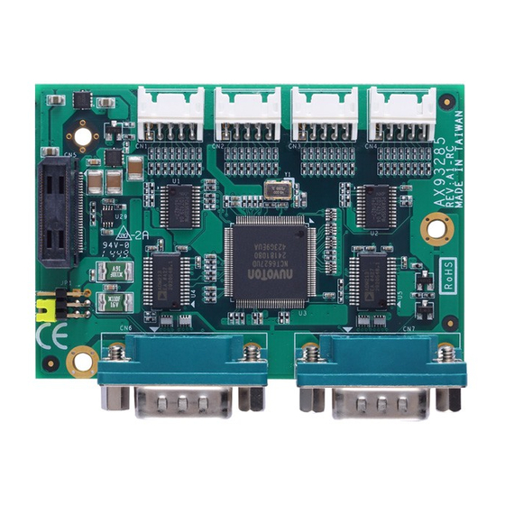
Dimension and Fixing Holes
Module Layout
Connectors
Connector
Description
CN1~CN4
Digital I/O Connectors
CN5
ZIO Expansion Connector
CN6
COM1 Connector
CN7
COM2 Connector
94193285000E
©
Copyright 2015 Axiomtek Co., Ltd.
Version A1 April 2015
Printed in Taiwan
1
Advertisement
Table of Contents

Related Manuals for AXIOMTEK AX93285


Summary of Contents for AXIOMTEK AX93285
- Page 1 AX93285 ZIO Module Quick Installation Guide Register 0 and 1: Input port 0 and 1 registers (input-only port). It reflects the incoming logic levels of the pins, regardless of whether the pin is defined as an input or an output. Writes to this register have no effect.
- Page 2 DI2/10/18/26 DI6/14/22/30 DI1/9/17/25 DI7/15/23/31 DI0/8/16/24 Jumper Settings ZIO Expansion Connector (CN5) Before applying power to AX93285, please make sure all jumper(s) are in The CN5 is for connecting ZIO module to CPU board. factory default positions. Signal Signal Jumper Description...
Need help?
Do you have a question about the AX93285 and is the answer not in the manual?
Questions and answers