Table of Contents
Advertisement
Available languages
Available languages
Quick Links
User Manual
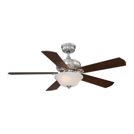
1.32 m (52 in.)
Selena Lighted Ceiling Fan
MODELS: 20390 & 20406
120V 60Hz, MADE IN CHINA
Customer Assistance
1-866-885-4649
re Service Team at 1-866-885-4649
re 9:00AM-5:00PM EST -Monday-Friday
r
Note: Installation videos for fans with GE Powerplug quick connection technology
can be viewed and downloaded
on www.gelightingandfans.com
Advertisement
Table of Contents

Related Manuals for GE 20390


Summary of Contents for GE 20390
- Page 1 Selena Lighted Ceiling Fan MODELS: 20390 & 20406 120V 60Hz, MADE IN CHINA Customer Assistance 1-866-885-4649 re Service Team at 1-866-885-4649 re 9:00AM-5:00PM EST -Monday-Friday Note: Installation videos for fans with GE Powerplug quick connection technology can be viewed and downloaded on www.gelightingandfans.com...
-
Page 2: Safety Rules
Safety Rules READ AND SAVE THESE INSTRUCTIONS 1. To reduce the risk of electric shock, ensure electricity has WARNING: To reduce the risk of fire, electric shock or personal been turned off at the circuit breaker or fuse box before injury, mount fan to outlet box beginning of installation. - Page 3 Basic Guidelines For Working With Electricity 1. Before working on a circuit, go to the main service panel and remove the fuse or turn off the breaker that controls that circuit. 2. Tape a sign to the panel warning others to leave the circuit alone while you work.
- Page 4 To Begin / Tools Needed (Not Supplied) REQUIRED Flathead Phillips Screwdriver Safety Glasses Screwdriver (4" recommended) Pliers Wire Cutters Electrical Tape Step Ladder Wire Strippers Soft Cloth...
-
Page 5: Hardware Included
Hardware Included Carefully unpack and identify each part to make sure you ATTENTION: Parts are not to scale. have everything ready for installation. Lay out each part on a clean flat area such as a table or floor. Check to make sure you have the following: Hardware Bag Remote Control... -
Page 6: Package Contents
Package Contents Carefully unpack and identify each part to make sure you ATTENTION: Parts are not to scale. have everything ready for installation. Lay out each part on o l f you have the following: Functional Fasteners PART DESCRIPTION QUANTITY Powerplug receptacle Canopy assembly Canopy trim ring... - Page 7 Fan Installation Drawing WARNING: Review important safety instructions before installation. Outlet box (not provided) Neutral white wire Black wire Rubber washer Ground wire Locking pin terminal Powerplug receptacle Flat washer J slot Wood screw Outlet box screw Plug locking pin Canopy mounting screw Mounting bracket push lever Ground wire from mounting bracket...
-
Page 8: Fan Installation
Fan Installation MAKING THE ELECTRICAL CONNECTIONS Prepare wiring from outlet box. Be sure there are no Fig 1 deep cuts in the exposed copper wiring as it could break off in the terminals. Cut and strip 1/2 in. of insulation from end of each wire if necessary. (Fig 1) outlet box NOTE: Do NOT strip any more than 1/2 in. - Page 9 Fan Installation WARNING: To avoid possible WIRING DIAGRAM 3: electric shock, be sure electricity is Wiring Configuration with more than 1 of the same turned off at the main fuse box colored wires in the outlet box before wiring. black NOTE: Fan must be installed at (L1) wire nut...
- Page 10 Fan Installation INSTALLING THE POWERPLUG RECEPTACLE WITH RUBBER WASHER It is important for the powerplug receptacle to be flush with the ceiling surface. Outlet boxes are typically not even with the surface or sheet rock and the rubber washers will help to reduce or eliminate the gap. Follow these instructions.
-
Page 11: Hanging The Fan
Fan Installation HANGING THE FAN rubber insert Remove the cotter pin (R) and clevis pin (Q from the downrod of Remove the rubber insert located on the canopy the canopy assembly (B). mounting screws (N) on both sides before installation. Note: For installation and use of longer downrod (option sold separately), instructions are available at www.gelightingandfans.com... -
Page 12: Finishing The Fan Installation
Fan Installation FINISHING THE FAN INSTALLATION Groove Rotate the canopy to the right (clockwise), continue Make sure the tab on the mounting bracket socket is properly seated in the groove in the hanger ball/ turning the canopy until the screws (O) lock into downrod assembly. -
Page 13: Installing The Light Kit Assembly
Fan Installation Note: Before starting installation, disconnect the power by turning off the circuit breaker or removing the fuse at fuse box. Turning power off using the fan switch is not sufficient to prevent electric shock. Remove the three switch housing screws (S) preassembled on mounting plate of motor housing and save for later use. Note: To install the fan with light kit assembly, proceed to steps below. -
Page 14: Remote Control Operations
Operation Instructions REMOTE CONTROL OPERATIONS Step 1. Restore power at circuit breaker and turn the wall switch to the on position (if using wall switch) to test for proper operation, Step 2. Open the battery compartment cover, and then install two 1.5-volt AAA batteries (KK) provided in the remote control bag. - Page 15 Operation Instructions FAN REVERSE FUNCTION The reversible motor provides upward and downrod air flow for desired air circulation to save energy, see below for the details. Warm weather - Switch to the “Forward” Cool weather - Switch to the “Reverse” position: A downward air flow creates a position: An upward air flow moves warm cooling effect as shown.
- Page 16 Remote Control Pairing Instructions REMOTECONTROLPAIRINGINSTRUCTIONS Important Note : By default, every fan has been pre-programmed at the factory and should be fully functional once installation is completed. There is no need to perform the pairing process. Should you find the fan or remote control not working or not fully functional after installation or during use, pairing of the remote control can be done by following the below simple procedures.
-
Page 17: Blade Balancing
Blade Balancing The following procedure should correct most fan wobble. Check after each step. Check that all blade and blade bracket screws are secure. Most fan wobble problems are caused when blade levels are unequal. Check this level by selecting a point on the ceiling above the tip of one of the blades. - Page 18 Blade Balancing Kit The balancing kit should only be used if there is an unacceptable amount of fan wobble after completing all the steps in the user manual under “Attaching the Fan Blades”. 1. Turn the fan on and set the speed control setting to the speed at which the wobble is the greatest.
-
Page 19: Safety Instructions
There is no need to oil your fan. The motor has permanently lubricated sealed ball bearings. Note: Installation videos for fans with GE Powerplug quick connection technology can be viewed and download on www.gelightingandfans.com TROUBLESHOOTING... -
Page 20: Manual Del Usuario
Service Team at 1-866-885-4649 re 9:00AM-5:00PM EST -Monday-Friday Nota: Videos de Instalación para ventiladores con la tecnología de instalación Note: Installation videos for fans with GE Powerplug quick connection technology rápida con enchufe GE pueden ser vistos y descargados en www.gelightingandfans.com can be viewed and downloaded on www.gelightingandfans.com... -
Page 21: Para Su Seguridad
Para su seguridad LEA Y GUARDE ESTAS INSTRUCCIONES 1. Para reducir el riesgo de descarga eléctrica, asegúrese de ADVERTENCIA: para reducir el riesgo de incendios, descargas que la electricidad se haya apagado en el disyuntor o caja de eléctricas o lesiones personales, fusibles antes de comenzar de instalación. - Page 22 Guías Básicas Para Trabajar Con Electricidad 1. Antes de trabajar en un circuito, vaya al panel de servicio principal y retire el fusible o active el disyuntor que controla ese circuito. 2. Pegue una señal en el panel que advierta a otras personas que se alejen del ci rcuito mientras usted trabaja 3.
- Page 23 Herramientas Necesarias (No suministradas) NECESARIO Destornillador de Destornillador de Gafas de Seguridad Cabeza Plana Estrella o Phillips (4” recomendado) Alicates Cortadores de Cinta Eléctrica Cable Escalera Pelacables Paño Suave...
-
Page 24: Herrajes Incluidos
Herrajes Incluidos Desempaque con cuidado e identifiq ue cada una de las ATENCIÓN: Las piezas no están a piezas para que se asegure de que tiene todo listo para la escala. instalación. Coloque todas las piezas en una superficie limpia y plana, como una mesa o alfombra. -
Page 25: Contenido Del Paquete
Contenido del Paquete Desempaque con cuidado e identi que cada una de las piezas ATENCIÓN: Las piezas no están a escala. para que se asegure de que tiene todo listo para la instalación. Coloque todas las piezas en una super cie limpia y plana, como o f l Sujetadores funcionales PARTE... - Page 26 Dibujo de la instalación del ventilador ADVERTENCIA: Revise las instrucciones de seguridad importantes antes de la instalación Caja eléctrica (no suministrada) Cable negro Cable blanco neutral Cable a tierra Arandela plana Receptáculo del enchufe eléctrico Terminal de pasador de bloqueo Ranura de J Tornillo de madera Pasador de bloqueo...
-
Page 27: Cómo Hacer Las Conexiones Eléctricas
Instalación del ventilador CÓMO HACER LAS CONEXIONES ELÉCTRICAS Prepare el cableado de la caja eléctrica. Asegúrese Fig 1 de que no haya cortes profundos en el cableado de cobre expuesto pues estos se podrían partir en los terminales. Corte y pele 1/2 pulgada de la insulación de los extremos de cada cable si es necesario. - Page 28 Instalación del ventilador DIAGRAMA DE CABLEADO 3 ATENCION: Para prevenir un posible Configuración de Cableado con más de 1 cable corto circuito, asegúrese que el flujo del mismo color en la caja eléctrica. eléctrico esté apagado en el panel principal de la caja de fusibles antes de realizar el cableado negro NOTA: El ventilador deberá...
- Page 29 Instalación del ventilador INSTALANDO EL RECEPTÁCULO DEL ENCHUFE ELÉCTRICO CON LAS ARANDELAS DE GOMA Es importante que el receptáculo del enchufe eléctrico este empotrado a la superficie del techo. Las cajas eléctricas típicamente no están parejas con el techo y las arandelas de goma ayudarán a reducir o eliminar cualquier espacio.
- Page 30 Instalación del ventilador ENSAMBLAR EL VENTILADOR Pieza de goma Retire la chaveta (R) y el pasador de horquilla (Q) del tubo del Retire las piezas de goma localizadas en los tornillos conjunto del dosel (B). de montaje del dosel (O) en ambos lados antes de la Nota: Para la instalación y el uso de un tubo mas largo (opción instalación.
- Page 31 Instalación del ventilador TERMINANDO LA INSTALACION DEL VENTILADOR Lengüeta Ranura Asegúrese que la lengüeta en el receptáculo del soporte Gire el dosel a la derecha (sentido horario) , siga girando de montaje caiga apropiadamente en la ranura en el el dosel hasta que los tornillos (O) encajen en las conjunto de bola / conjunto de varilla.
- Page 32 Instalación del ventilador Nota: Antes de comenzar la instalación, desconecte la energía apagando el disyuntor o retirando el fusible de la caja de fusibles. Apagar la energía utilizando el interruptor del ventilador no es suficiente para evitar una descarga eléctrica. Retire los tres tornillos de la cubierta del interruptor (S) preinstalado al plato de montaje de la cubierta del motor y guárd elos para ser usados mas tarde.
-
Page 33: Instrucciones De Operación
Instrucciones de Operación FUNCIONAMIENTO DEL CONTROL REMOTO Paso 1. Restablezca la electricidad en el panel de fusibles y encienda el interruptor de pared (si usa un interruptor de pared) para probar el funcionamiento adecuado. Paso 2. Abra la tapa del compartimento de las baterías, e instale dos baterías AAA de 1.5 volts (M) provistas en la bolsa del control remoto. - Page 34 Instrucciones de Operación FUNCION DE REVERSA DEL VENTILADOR El motor reversible provee un flujo de aire descendente or ascendente para la circulacion de aire deseada para ahorrar energia, vea a continuacion para mas detalles. Clima cálido - Cambie a la pocision "Adelante". Clima frío - Cambie a la posicion de "Reverso": Un flujo de aire descendente crea un efecto Un flujo de aire ascendente desde el techo tal...
- Page 35 Instrucciones Para la Sincronización del Control Remoto INSTRUCCIONES PARA LA SINCRONIZACIÓN DEL CONTROL REMOTO Nota Importante: De manera estandar cada ventilador ha sido configurado en la fábrica y debe funcionar sin problemas una vez este haya sido instalado completamente. No se require el processo de sincronización.
-
Page 36: Balanceo De Las Aspas
Balanceo de las aspas El siguiente procedimiento debe corregir la mayor parte del tambaleo del ventilador. Compruebe después de cada paso. Compruebe que todos los tornillos de las aspas y de los soportes de las aspas estén asegurados. La mayoría de los problemas del tambaleo se originan cuando los niveles de las aspas son desiguales. - Page 37 Juego de Balance de las Aspas Blade Balancing Kit Equipo de balanceo El kit de balanceo de las aspas solo se debe usar si hay tambaleos del ventilador luego de haber terminado todos los pasos de la instalación del ventilador en el manual bajo "Cómo colocar las aspas del ventilador".
-
Page 38: Solucion De Problemas
Cubra pequeños arañazos con una ligera aplicación de pintura. No hay necesidad de aceitar su ventilador. El motor lubrica permanentemente los rodamientos. Nota: Usted podrá ver y descargar videos para la instalación del ventilador con el conector eléctrico GE en la página www.gelightingandfans.com SOLUCION DE PROBLEMAS PROBLEMA SOLUCIÓN -Verifique los fusibles de los circuitos central y derivado.
Need help?
Do you have a question about the 20390 and is the answer not in the manual?
Questions and answers