Table of Contents
Advertisement
Quick Links
Advertisement
Table of Contents

Related Manuals for Haltech NEXUS R5


Summary of Contents for Haltech NEXUS R5
- Page 1 QUICK START GUIDE...
-
Page 2: What's In The Box
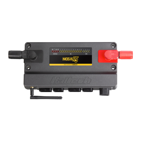
• Wideband Flying Lead Adaptor Harness 400mm. HT-010723 • LSU4.9 Wideband Adaptor Harness 1200mm. HT-010726 The NEXUS R5 is Haltech’s new flagship • LSU4.9 Wideband Hardware Pack. Inc sensor, adaptor harness and weld-in bung. HT-010746 product. Boasting new, innovative yet •... - Page 3 NEXUS R5 OVERVIEW NEXUS R5 LED BEHAVIOUR 1 Power LED COLOUR CONDITION 2 DTC LED Power Green Normal operation (on main power or low power mode) 3 Wi-Fi LED Blue Connect to unit and install firmware 4 Datalog LED 5 8A HCO LEDs Hardware fault...
- Page 4 NEXUS R5 SPECIFICATIONS OUTPUTS COMMUNICATIONS Ignition CAN Bus Networks 1000, 500 or 250 kbit/s Injector (peak and hold) High Speed USB 2.0 (USB-C interface) 480 Mbit/s connection Digital Pulsed Outputs (DPO) Power up over USB Datalogging, settings and firmware upgrade available Power for Ignition Switch Wi-Fi 900 kB/s datalog extraction. Hardware lockout for security...
-
Page 5: Installing The Software
1AWG cable. the Haltech NSP software from the DOWNLOADS 1. Open NSP and connect to your NEXUS R5 via powering the ECU completely. ECU inputs and section of the Haltech website. the supplied USB-C cable. -
Page 6: Main Power
MOUNTING TEMPLATE Main Power The NEXUS R5 must be connected to battery positive and battery negative at all times for correct operation. • Connect the NEXUS R5 to the positive battery IGNITION IGNITION SWITCH SWITCH terminal via the supplied RED SurLok connector... -
Page 8: Ignition Outputs
Ignition Outputs Ignition outputs must be connected directly to MOUNTING TEMPLATE an ignition module to control the ignition of the IGN 1 vehicle. Do not connect directly to a coil without an internal or external ignition module as doing this will IGN 2 DIRECT FIRE IGNITION damage the ECU. - Page 9 Digital Pulsed Outputs (DPO) NEXUS R5 WIRING HBO 1 Digital Pulsed Outputs are capable of producing pulsed waveforms with varying duty and INJ #1 HBO 2 frequency. When a Digital Pulsed Output is activated by the Injection Outputs INJ #2 ECU the output will switch to ground.
- Page 10 8A High Current Outputs (8A HCO) NEXUS R5 WIRING Example Wiring Connections Example Wiring Connections THERMOFAN The NEXUS R5 features 12 high side outputs which are capable of driving 8A to 12V. Hall E ect Sensor Crank (Trigger) and Cam (Home) Inputs +12V...
-
Page 11: Signal Ground
SIGNAL GROUND AVI inputs can tolerate a maximum input voltage Specs: • 1 million samples per second The NEXUS R5 ECU uses the knock sensor signal SENSOR +5V of 30V. • -2.5 to 2.5V AC input only • Selectable 1k pull-up to 5V to modify ignition timing if knocking occurs. -
Page 12: Warranty Certificate
• -40 to 40V short protection battery charger connected as this could damage the ECU and other electrical equipment. If the Haltech product is found to be defective as mentioned above, it will be replaced or repaired resistor. if returned prepaid along with proof of purchase. Proof of purchase in the form of a copy of the Do not overcharge the battery or reverse the polarity of the battery or any charging unit. - Page 13 03/2023 Haltech Australia 17 Durian Place, Wetherill Park NSW 2164 Australia Phone: +61 2 9729 0999 Email: aus@haltech.com Haltech New Zealand 9B Weza Lane, Kumeu 0810 NZ Phone: 09 887 0616 Email: nz@haltech.com Haltech USA East 750 Miles Point Way,...