
Related Manuals for SMA MD.SEN-40


Summary of Contents for SMA MD.SEN-40
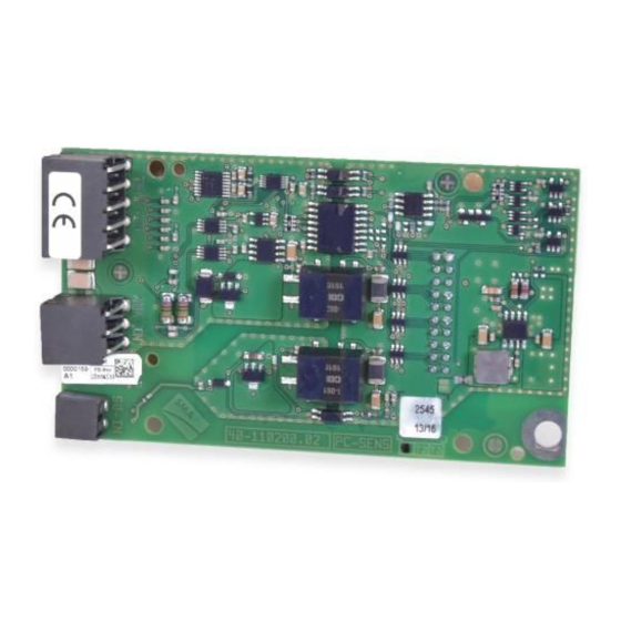
- Page 1 Installation Manual SMA SENSOR MODULE MD.SEN-40 (PC-SENS.BG1) ENGLISH MDSEN-40-IA-en-11 | Version 1.1...
- Page 2 SMA Solar Technology AG Legal Provisions The information contained in these documents is the property of SMA Solar Technology AG. No part of this document may be reproduced, stored in a retrieval system, or transmitted, in any form or by any means, be it electronic, mechanical, photographic, magnetic or otherwise, without the prior written permission of SMA Solar Technology AG.
-
Page 3: Table Of Contents
SMA Solar Technology AG Table of Contents Table of Contents Information on this Document..........Validity ........................Target Group......................Content and Structure of this Document ..............Levels of Warning Messages ..................Symbols in the Document ..................Typographical Elements in the Document .............. - Page 4 Table of Contents SMA Solar Technology AG Disposing of the Product.................... 29 Technical Data ................30 10 Contact ..................32 MDSEN-40-IA-en-11 Installation Manual...
-
Page 5: Information On This Document
1 Information on this Document Information on this Document Validity This document is valid for: • SMA Sensor Module (MD.SEN-40) with assembly designation "PC-SENS.BG1" from hardware version A1. Target Group The tasks described in this document must only be performed by qualified persons. Qualified persons must have the following skills: •... -
Page 6: Symbols In The Document
1 Information on this Document SMA Solar Technology AG Symbols in the Document Symbol Explanation Information that is important for a specific topic or goal, but is not safety-rele- vant Indicates a requirement for meeting a specific goal ☐ Desired result ☑... -
Page 7: Safety
All components must remain within their permitted operating ranges and their installation requirements at all times. The product must only be used in countries for which it is approved or released by SMA Solar Technology AG and the grid operator. -
Page 8: Important Safety Instructions
2 Safety SMA Solar Technology AG IMPORTANT SAFETY INSTRUCTIONS Keep the manual for future reference. This section contains safety information that must be observed at all times when working. The product has been designed and tested in accordance with international safety requirements. As with all electrical or electronical devices, there are residual risks despite careful construction. -
Page 9: Scope Of Delivery
SMA Solar Technology AG 3 Scope of Delivery Scope of Delivery Check the scope of delivery for completeness and any externally visible damage. Contact your distributor if the scope of delivery is incomplete or damaged. Figure 1: Components included in scope of delivery... -
Page 10: Product Overview
Product Overview Product Description The SMA Sensor Module is a module for SMA inverters. The SMA Sensor Module has different interfaces for connecting various sensors. The SMA Sensor Module converts the signals of the connected sensors and transmits them to the inverter. The sensors are not included in the SMA Sensor Module's scope of delivery. -
Page 11: Type Label
SMA Solar Technology AG 4 Product Overview Position Designation Explanation Terminals for the temperature measurement TEMP-IN – Connector strip on the back of the module for connection to the communication assembly in the inverter Type Label The type label clearly identifies the product. The type label is located on the front of the product. -
Page 12: Mounting
Communication assembly Module slot M1* Module slot M2 * Production resources SMA Solar Technology AG recommends using module slot M1 for the module. Installing the Module Maximum number of modules of the same device type per inverter You can only use a maximum of 1 SMA Sensor Module per inverter. - Page 13 SMA Solar Technology AG 5 Mounting • Guide the 3 guide pins on the communication assembly through the holes in the module. The holes in which the guide pins must be inserted depend on the module slot. • Carefully push the module down on the upper...
-
Page 14: Connection
6 Connection SMA Solar Technology AG Connection Safety during Electrical Connection DANGER Danger to life due to high voltages of the PV array When exposed to light, the PV array generates dangerous DC voltage, which is present in the DC conductors and the live components of the inverter. Touching the DC conductors or the live components can lead to lethal electric shocks. -
Page 15: Preparing The Connection Cable
SMA Solar Technology AG 6 Connection Cable type Requirements Connection cable for ☐ Number of conductors: at least 2 analog input ☐ Shielding: yes ☐ Conductor cross-section: 0.2 mm² to 1.5 mm² ☐ Maximum cable length: 30 m Connection cable for ☐ Number of conductors: 2 S0 interface ☐... -
Page 16: Preparing The Enclosure Opening On The Inverter
6 Connection SMA Solar Technology AG 4. For each connection cable, cut 40 mm from the 120 mm cable for shielding. 1 2 0 ( 4 . 7 1 ( 1 . 5 7 ( 1 . 5 7 ( 1 . 5 7 5. -
Page 17: Connecting The Temperature Sensor
SMA Solar Technology AG 6 Connection 5. Press the seal out of the cable gland from the inside. 6. Remove the filler plugs from the 4-hole seal depending on the number of connection cables and store safely for later decommissioning. - Page 18 6 Connection SMA Solar Technology AG Temperature input Signal Explanation Module temperature Shield ground Current output Voltage input V− Voltage return I− Current return Circuitry overviews: Temperature sensor with Pt100 or Pt1000 Shield measuring shunt SMA Sensor Module A2 (B2) A3 (B3) ϑ...
-
Page 19: Connecting An Irradiation Sensor
SMA Solar Technology AG 6 Connection Procedure: 1. Connect the connection cable to the temperature sensor (see the manual from manufacturer). Trim the unneeded insulated conductors up to the cable shield and note down the conductor colors. 2. On the 5-pole terminal block, unlock the terminal... - Page 20 6 Connection SMA Solar Technology AG ☐ The connection cable must be prepared for connection to the multipole terminal block (see Section 6.3, page 15). Pin assignment: Figure 8: Pin assignment for terminal ANA-IN Signal Explanation Voltage input Current input Reference potential of the supply voltage...
- Page 21 SMA Solar Technology AG 6 Connection Irradiation sensor with voltage output Shield SMA Sensor Module 24 V 100 kΩ Figure 10: Connection of an irradiation sensor with voltage output Procedure: 1. Connect the connection cable to the irradiation sensor (see the manual from manufacturer).
-
Page 22: Connecting The Anemometer Or Energy Meter
6 Connection SMA Solar Technology AG Connecting the Anemometer or Energy Meter You can connect a maximum of 1 remote terminal with S0 impulse output to the module, e.g. 1 anemometer or 1 energy meter. Additionally required material (not included in the scope of delivery): ☐... - Page 23 SMA Solar Technology AG 6 Connection • 40 mmPeel cable sheath. Make sure that no pieces of cable are dropped into the inverter. • Strip off the conductor insulation by 6 mm. • On the 2-pole terminal block, unlock the required terminal positions using a suitable tool ( ) and plug the conductors of the connection cable into these terminal positions ( ).
-
Page 24: Configuration
7 Configuration SMA Solar Technology AG Configuration Configuring the Anemometer or Energy Meter You must configure the S0 input of the module depending on the signal source used (anemometer or energy meter). To ensure that correct measured values are displayed, you must set the number of pulses per second. -
Page 25: Configuring The Temperature Sensor
SMA Solar Technology AG 7 Configuration Configuring the Temperature Sensor If temperature sensors for module temperature and/or ambient temperature are connected, the inverter automatically detects the type of temperature sensors connected and activates the measurement mode. You can configure the display of the temperature display on the start page of the user interface in the event of an error (e.g. -
Page 26: Configuring The Irradiation Sensor
7 Configuration SMA Solar Technology AG 4. In the context menu, select [Starting the installation assistant]. 5. Select [Save and next] until you reach the Irradiation temperature step. 6. Under Module temperature and External temperature, select the required setting value for the temperature display in the event of an error. - Page 27 SMA Solar Technology AG 7 Configuration Object name Parameter Display group Settings Y value 1 of charac- Device > Inputs/outputs > • 0.000 to Out.AnIn.YVal1- teristic curve of the Analog input > Y value 1 1500.000 W/m² NoUnt analog input Y value 2 of charac- Device >...
-
Page 28: Decommissioning
8 Decommissioning SMA Solar Technology AG Decommissioning Removing the Module DANGER Danger to life due to high voltages of the PV array When exposed to sunlight, the PV array generates dangerous DC voltage, which is present in the DC conductors and the live components of the inverter. Touching the DC conductors or the live components can lead to lethal electric shocks. -
Page 29: Packing The Product For Shipment
SMA Solar Technology AG 8 Decommissioning • Slightly press the second locking tab outwards using the other hand and pull the module slightly forwards on the lower end until the module is released from the interlock of the locking tab. - Page 30 9 Technical Data SMA Solar Technology AG Technical Data General Data Mounting location In the inverter Voltage supply Via the inverter Mechanical data Width x height x depth 60 mm x 105 mm x 33 mm Ambient conditions for storage/transport Ambient temperature -40°C to +70°C Relative humidity, non-condensing...
- Page 31 SMA Solar Technology AG 9 Technical Data Measurement range of the current input 0 mA to 20 mA Load resistance of the current input 450 Ω Typical measurement accuracy ±0.3 % Maximum measurement error +2.0 % Maximum cable length 30 m Supply voltage for irradiation sensor...
- Page 32 10 Contact SMA Solar Technology AG 10 Contact If you have technical problems with our products, please contact the SMA Service Line. The following data is required in order to provide you with the necessary assistance: • Inverters: – Serial number – Special country-specific settings (if available) •...
- Page 34 www.SMA-Solar.com...
Need help?
Do you have a question about the MD.SEN-40 and is the answer not in the manual?
Questions and answers