
Related Manuals for SMA MD.SEN-40


Summary of Contents for SMA MD.SEN-40
- Page 1 Installation Manual SMA SENSOR MODULE MD.SEN-40 (PC-SENS.BG1) ENGLISH MDSEN-40-IA-en-10 | Version 1.0...
- Page 2 The information contained in these documents is property of SMA Solar Technology AG. Any publication, whether in whole or in part, requires prior written approval by SMA Solar Technology AG. Internal reproduction used solely for the purpose of product evaluation or other proper use is allowed and does not require prior approval.
-
Page 3: Table Of Contents
SMA Solar Technology AG Table of Contents Table of Contents Information on this Document..........Validity ....................Target Group ..................Symbols....................Typographies ..................Nomenclature ..................Safety ..................Intended Use..................Safety Information ................Scope of Delivery ..............Product Description ..............10 SMA Sensor Module................. 10 Type Label.................. - Page 4 Table of Contents SMA Solar Technology AG Contact ..................30 MDSEN-40-IA-en-10 Installation Manual...
-
Page 5: Information On This Document
1 Information on this Document Information on this Document Validity This document is valid for the SMA Sensor Module (MD.SEN-40) with assembly designation "PC- SENS.BG1" from hardware version A1. You can find the latest version of this document at www.SMA-Solar.com. -
Page 6: Typographies
1 Information on this Document SMA Solar Technology AG Typographies Typography Example bold • Display texts • The value can be found in the field Energy. • Elements on a user interface • Select Settings. • Terminals • Enter 10 in the field •... -
Page 7: Safety
DIN EN 62053-31 (IEC 62053-31). A list with SMA Sensor Module compatible products is available at www.SMA-Solar.com. The product must only be used in countries for which it is approved or released by SMA Solar Technology AG and the grid operator. All components must remain within their permitted operating ranges at all times. -
Page 8: Safety Information
2 Safety SMA Solar Technology AG Safety Information This section contains safety information that must be observed at all times when working on or with the product. To prevent personal injury and property damage and to ensure long-term operation of the product, read this section carefully and observe all safety information at all times. -
Page 9: Scope Of Delivery
SMA Solar Technology AG 3 Scope of Delivery Scope of Delivery Check the scope of delivery for completeness and any externally visible damage. Contact your distributor if the scope of delivery is incomplete or damaged. Figure 1: Components included in the scope of delivery... -
Page 10: Product Description
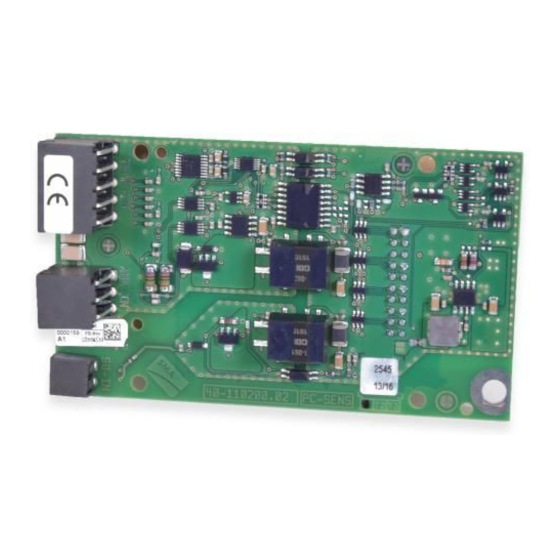
Product Description SMA Sensor Module The SMA Sensor Module is a module for SMA inverters. The SMA Sensor Module has different interfaces for connecting various sensors. The SMA Sensor Module converts the signals of the connected sensors and transmits them to the inverter. -
Page 11: Type Label
SMA Solar Technology AG 4 Product Description Position Designation Explanation TEMP-IN Terminals for the temperature measurement – Connector strip on the back of the module for connection to the communication assembly in the inverter Type Label The type label clearly identifies the product. The type label is located on the front of the product. -
Page 12: Mounting
Communication assembly Module slot M1* Module slot M2 * Either of the two module slots can be used for the SMA Sensor Module. SMA Solar Technology AG recommends using module slot M1 for the SMA Sensor Module. Installing the Module Maximum number of modules of the same device type per inverter You can only use a maximum of one SMA Sensor Module per inverter. - Page 13 SMA Solar Technology AG 5 Mounting 2. To achieve an optimum WLAN range, the module should ideally be installed on module slot M1. Perform the following steps: • Guide the three guide pins on the communication assembly through the holes in the module.
-
Page 14: Connection
6 Connection SMA Solar Technology AG Connection Safety during Electrical Connection Danger to life due to high voltages of the PV array When exposed to sunlight, the PV array generates dangerous DC voltage, which is present in the DC conductors and the live components of the inverter. Touching the DC conductors or the live components can lead to lethal electric shocks. -
Page 15: Preparing The Connection Cable
SMA Solar Technology AG 6 Connection Cable type Requirements Connection cables for ☐ Number of insulated conductors for tolerance ±2°C: at least two temperature inputs ☐ Number of insulated conductors for tolerance ±0.5°C: at least four ☐ Shielding: yes ☐ Conductor cross-section with four-conductor connection technology: at least 4 x 0.25 mm²... - Page 16 6 Connection SMA Solar Technology AG 3. Press the shield clamp onto the cable shield. The cable shield must be clamped under the shield clamp as completely as possible. 4. For each connection cable, cut 40 mm from the 120 mm cable for shielding.
-
Page 17: Preparing The Enclosure Opening On The Inverter
SMA Solar Technology AG 6 Connection Preparing the Enclosure Opening on the Inverter Additionally required material (not included in the scope of delivery): ☐ Connection cable (see Section 6.2 "Cable Requirements", page 14) Procedure: 1. Make sure that the inverter has been disconnected and is secured against reconnection (see the inverter manual). - Page 18 6 Connection SMA Solar Technology AG Figure 5: Pin assignment for terminal TEMP-IN Temperature input Signal Explanation Outside temperature Shield ground Current output Voltage input V− Voltage return I− Current return Cell temperature Shield ground Current output Voltage input V− Voltage return I−...
- Page 19 SMA Solar Technology AG 6 Connection Circuitry overviews: Figure 6: Connection of a temperature sensor with four-conductor connection technology Figure 7: Connection of a temperature sensor with two-conductor connection technology Installation Manual MDSEN-40-IA-en-10...
-
Page 20: Connecting An Irradiation Sensor
6 Connection SMA Solar Technology AG Procedure: 1. Connect the connection cable to the temperature sensor (see the manual from manufacturer). Trim the unneeded insulated conductors up to the cable shield and note down the conductor colors. 2. On the 5-pole connecting terminal plate, unlock... - Page 21 SMA Solar Technology AG 6 Connection Requirements: ☐ The irradiation sensor must be technically suitable for connection to the analog input (see Section 8, page 28). ☐ The connection cable must be prepared for connection to the multipole terminal block (see Section 6.3, page 15).
- Page 22 6 Connection SMA Solar Technology AG Circuitry overviews: Figure 9: Connection of an irradiation sensor with current output Figure 10: Connection of an irradiation sensor with voltage output Procedure: 1. Connect the connection cable to the irradiation sensor (see the manual from manufacturer).
-
Page 23: Connecting The Remote Terminal To The S0 Interface
SMA Solar Technology AG 6 Connection 3. On the first 3-pole connecting terminal plate, unlock the required terminal positions using a suitable tool ( ) and plug the conductors into these terminal positions ( 4. On the second 3-pole connecting terminal plate, unlock the terminal position 1 using a suitable tool and plug the conductor of the cable piece for shielding into this terminal position. - Page 24 6 Connection SMA Solar Technology AG Pin assignment: Figure 11: Pin assignment for terminal S0-IN Signal Explanation S0– Input for S0 signal Current-supplying output for supplying the S0 signal Circuitry overview: Figure 12: Circuitry overview for the connection of a remote terminal to the S0 interface Procedure: 1.
- Page 25 SMA Solar Technology AG 6 Connection • On the 2-pole connecting terminal plate, unlock the required terminal positions using a suitable tool ( ) and plug the conductors of the connection cable into these terminal positions ( ). Observe the pin assignment.
-
Page 26: Decommissioning
7 Decommissioning SMA Solar Technology AG Decommissioning Removing the Module Procedure: Danger to life due to high voltages of the PV array When exposed to sunlight, the PV array generates dangerous DC voltage, which is present in the DC conductors and the live components of the inverter. Touching the DC conductors or the live components can lead to lethal electric shocks. -
Page 27: Packing The Product For Shipment
SMA Solar Technology AG 7 Decommissioning • Slightly press the second locking tab outwards using the other hand ( ) and pull the module slightly forwards on the lower end ( ) until the module is released from the interlock of the locking tab. -
Page 28: Technical Data
8 Technical Data SMA Solar Technology AG Technical Data General Data Mounting location In the inverter Voltage supply Via the inverter Mechanical data Width x height x depth 60 mm x 105 mm x 33 mm Ambient conditions for storage/transport Ambient temperature -40°C to +70°C Relative humidity, non-condensing... - Page 29 SMA Solar Technology AG 8 Technical Data Input resistance of the voltage input 100 kΩ Measurement range of the current input 0 mA to 20 mA Load resistance of the current input 450 Ω Typical measurement accuracy ±0.3 % Maximum measurement error +2.0 % Maximum cable length 30 m...
- Page 30 9 Contact SMA Solar Technology AG Contact If you have technical problems with our products, please contact the SMA Service Line. We require the following information in order to provide you with the necessary assistance: • Inverters: – Serial number – Firmware version –...
- Page 31 +562 2820 2101 08600SUNNY (08600 78669) Perú International: +27 (0)21 826 0600 SMA Online Service Center: www.SMA-Service.com Australia SMA Australia Pty Ltd. Other countries International SMA Service Line Sydney Niestetal Toll free for Australia: 00800 SMA SERVICE 1800 SMA AUS (+800 762 7378423) (1800 762 287) International: +61 2 9491 4200...
- Page 32 www.SMA-Solar.com...
Need help?
Do you have a question about the MD.SEN-40 and is the answer not in the manual?
Questions and answers