SMA SUNNY HOME MANAGER 2.0 Operating Manual
Hide thumbs
Also See for SUNNY HOME MANAGER 2.0:
- Quick reference manual (2 pages) ,
- Operating manual (127 pages) ,
- Operating manual (86 pages)
Table of Contents
Advertisement
Quick Links
Advertisement
Table of Contents

Related Manuals for SMA SUNNY HOME MANAGER 2.0


Summary of Contents for SMA SUNNY HOME MANAGER 2.0
- Page 1 Operating manual SUNNY HOME MANAGER 2.0 ENGLISH HM-20-BE-en-19 | Version 1.9...
- Page 2 Legal Provisions The information contained in these documents is the property of SMA Solar Technology AG. No part of this document may be reproduced, stored in a retrieval system, or transmitted, in any form or by any means, be it electronic, mechanical, photographic, magnetic or otherwise, without the prior written permission of SMA Solar Technology AG.
-
Page 3: Table Of Contents
Components for Operating the Sunny Home Manager ................18 5.3.1 Basic Operation .............................. 18 5.3.2 Operation of a PV system with SMA inverters ..................... 18 5.3.3 Operation of a PV system with third-party inverters ..................19 5.3.4 Components for the control of loads ......................19 System Structure .......................... - Page 4 Enabling System Communication Monitoring ....................58 11.3.9 Setting the Data Request Interval ........................59 11.3.10 Activating SMA Smart Home ......................... 59 11.3.10.1 Activating the Self-Consumption Function ...................... 59 11.3.10.2 Setting up Forecast-Based Battery Charging....................60 11.3.11 Configuring the External Current Transformer....................61 11.3.12 Changing the Meter Configuration........................
- Page 5 SMA Solar Technology AG Table of Contents 11.4.2 Entering Line Conductors ..........................62 11.4.3 Entering the PV Array Power .......................... 63 11.5 Adding a Switching Device..........................63 11.5.1 Adding a Radio-Controlled Socket ........................ 63 11.5.2 Adding Modbus Device..........................64 11.6 Adding direct communicating loads....................... 65 11.6.1...
- Page 6 14.2 Configuring PV System Monitoring.........................106 14.2.1 Setting Communication Monitoring ....................... 106 14.2.2 Setting the Inverter Comparison........................106 14.2.3 Activating SMA Smart Connected ......................... 107 14.2.4 Editing the System Configuration ........................107 14.2.5 Filter and confirm messages in the system logbook ..................108 14.2.6 Configuring Reports ............................
- Page 7 SMA Solar Technology AG Table of Contents 19.3 Disposing of the Product..........................134 20 Application Examples........................135 20.1 Forecast-based battery charging ........................135 20.1.1 Objective and Background Information ......................135 20.1.2 Setting up Forecast-Based Battery Charging....................136 20.2 Heat Pumps with SG-Ready Interface ......................137 20.2.1...
-
Page 8: Information On This Document
1 Information on this Document SMA Solar Technology AG 1 Information on this Document Validity This document is valid for: • Sunny Home Manager 2.0 from software package 2.11.04.R Target Group This document is intended for qualified persons and end users. Only qualified persons are allowed to perform the activities marked in this document with a warning symbol and the caption "Qualified person". -
Page 9: Typographical Elements In The Document
Planning Guidelines The System Solution for Greater Independence "SMA SMART HOME - Battery Charging Management with Time-of-Use Energy Technical Information Tariffs" "SMA SMART HOME Load Control Using Relays or Contactors - Example: Heat- Technical Information ing Rod" SMA FLEXIBLE STORAGE SYSTEM System description Increased Self-Consumption with Sunny Island and Sunny Home Manager... -
Page 10: Safety
Alterations to the SMA products, e.g., changes or modifications, are only permitted with the express written permission of SMA Solar Technology AG. Unauthorized alterations will void guarantee and warranty claims and in most cases terminate the operating license. SMA Solar Technology AG shall not be held liable for any damage caused by such changes. - Page 11 SMA Solar Technology AG 2 Safety This section contains safety information that must be observed at all times when working. The product has been designed and tested in accordance with international safety requirements. As with all electrical or electronical devices, there are residual risks despite careful construction. To prevent personal injury and property damage and to ensure long-term operation of the product, read this section carefully and observe all safety information at all times.
-
Page 12: Cyber Security
NOTICE Manipulation of system data in networks You can connect the supported SMA products to the Internet. When connected to the Internet, there is a risk that unauthorized users can access and manipulate the data of your system. • Set up a firewall. -
Page 13: Service Description
SMA Solar Technology AG 3 Service Description 3 Service Description The field of applications for the Sunny Home Manager ranges from its use as a simple energy meter to monitoring a PV system and intelligent energy management. Sunny Home Manager as energy meter The Sunny Home Manager detects energy flows in both directions: •... - Page 14 Increased self-consumption through peak load shaving In systems with SMA battery or hybrid inverters, the self-consumption portion can be additionally increased and more electricity costs saved by virtually distributing the total storage capacity of the battery between increased self- consumption and peak load shaving (multi-use).
-
Page 15: Scope Of Delivery
SMA Solar Technology AG 4 Scope of Delivery 4 Scope of Delivery Check the scope of delivery for completeness and any externally visible damage. Contact your distributor if the scope of delivery is incomplete or damaged. S U N N Y H... -
Page 16: Product Overview
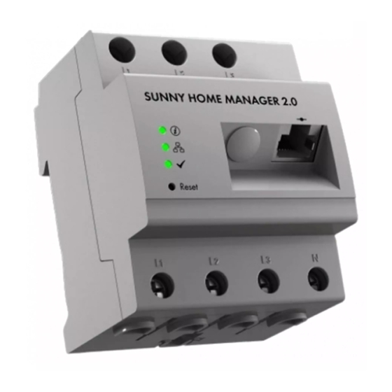
M A N O M E N Y H S U N R e s e t Reset Figure 2: Sunny Home Manager 2.0 Position Designation Connection area for line conductors and neutral conductor Light-emitting diodes Reset button Network terminal (Speedwire/Ethernet) -
Page 17: Type Label
SMA Solar Technology AG 5 Product Overview Position LED symbol Designation Explanation COM LED Displays the status of the Ethernet connection to the router Performance LED Displays the operating state, energy management, portal con- nection and error status. Sunny Home Manager operating states... -
Page 18: Components For Operating The Sunny Home Manager
5.3.2 Operation of a PV system with SMA inverters The Sunny Home Manager organizes the electricity generated by the PV system and provided by inverters within the loads in the household. The Sunny Home Manager regulates the feed-in of the residual current into the utility grid at the point of interconnection. -
Page 19: Operation Of A Pv System With Third-Party Inverters
☐ SMA inverters of type Sunny Boy Smart Energy and Sunny Tripower Smart Energy are not supported. If third-party inverters are also used in the PV system, the SMA Energy Meter handles the recording of the generated PV energy. In hybrid systems with SMA inverters and inverters from other manufacturers, the generated energy of all inverters is measured via the energy meter since it is used as the central PV generation meter. - Page 20 5 Product Overview SMA Solar Technology AG SMA offers the option to use the protocol interface SEMP under https://www.sma.de/produkte/sma- developer.html. HM-20-BE-en-19 Operating manual...
-
Page 21: System Structure
The router connects the Sunny Home Manager via the Internet to Sunny Portal. SMA recommends a permanent Internet connection (flat rate) and the use of a router that supports the dynamic assignment of IP addresses (DHCP ‒ Dynamic Host Configuration Protocol), e.g. a Fritz!Box. -
Page 22: Mounting
7 Mounting SMA Solar Technology AG 7 Mounting Requirements for Mounting the Sunny Home Manager ☐ The mounting location must be indoors. ☐ The Sunny Home Manager must be installed in a switch cabinet. The short-circuit current (circuit distributor or subdistributor) must not exceed 6 kA. -
Page 23: Connection
SMA Solar Technology AG 8 Connection 8 Connection Safety during Electrical Connection WARNING Risk of fire due to dirty or oxidized contact surfaces of live aluminum conductors Connecting dirty or oxidized contact surfaces with aluminum conductors reduces the ampacity of the live terminals, thereby increasing the transition resistances. -
Page 24: Connecting The Voltage Supply Up To 63 A
3 phase TN/TT 1 phase TN/TT Inverters L1 L2 L3 Household L1 L2 L3 L1 L2 L3 Delta-IT Sunny Home Manager 2.0 as purchased electricity and feed-in meter L1 L2 L3 L1 L2 L3 L1 L2 L3 Disconnect switch Split Phase... -
Page 25: Connecting The Voltage Supply Greater Than 63 A
• When only using it to measure the PV generation power: Connect the Sunny Home Manager to the common connection point of all PV inverters in the household grid. Information: To measure the grid exchange capacity, an SMA Energy Meter must be installed at the point of interconnection. -
Page 26: Establishing Communication To Sunny Portal
Establishing communication to Sunny Portal 8.3.1 Preparing for Speedwire Communication If the Sunny Home Manager is to communicate with other SMA devices via SMA Speedwire (Ethernet), the Sunny Home Manager and the Speedwire devices must be in the same local network. Inverters with Webconnect function If an inverter is already registered in Sunny Portal with the Webconnect function, the inverter cannot be added to... -
Page 27: Testing The Connection To Sunny Portal
SMA Solar Technology AG 8 Connection ☐ Cable type: 100BaseTx ☐ Cable category: minimum CAT5e ☐ Plug type: RJ45 of Cat5, Cat5e, Cat6 or Cat6a (Cat7 plugs cannot be used) ☐ Shielding: S/UTP, F/UTP or higher ☐ Number of insulated conductor pairs and insulated conductor cross-section: at least 2 x 2 x 0.22 mm²... - Page 28 8 Connection SMA Solar Technology AG Procedure: • Check the status of the LEDs. ☑ When both the Status and Performance LEDs glow green, you can log in to Sunny Portal with your user data (see Section 9.3, page 36). ☑ If only the Status LED glows green, but the Performance LED is off, you must first register the Sunny Home Manager in Sunny Portal and can then log in to Sunny Portal with your user data.
-
Page 29: Getting Started
SMA Solar Technology AG 9 Getting Started 9 Getting Started Creating a Sunny Home Manager System in Sunny Portal Sunny Portal is used as the user interface of the Sunny Home Manager. In general and in this document, systems equipped with a Sunny Home Manager are referred to as a "Sunny Home Manager system."... - Page 30 If inverters from other manufacturers are also installed in the PV system, an Energy Meter must be inserted between them. Only in this case you must select the entry SMA Energy Meter xxx in the drop-down list. Here, xxx is the placeholder for the SMA Energy Meter serial number. If there are several SMA Energy Meters in the PV system, select the required SMA Energy Meter.
- Page 31 SMA Solar Technology AG 9 Getting Started 24. Enter the Specific annual yield. You can obtain the specific annual yield for your system location from irradiation maps. 25. Enter the data for the location of the system. 26. Enter the Feed-in tariff if applicable.
-
Page 32: User Interface Of The Sunny Home Manager System
9 Getting Started SMA Solar Technology AG User Interface of the Sunny Home Manager System 9.2.1 Accessing the user interface If you have only created one system in Sunny Portal, you will automatically access the user interface of your system after logging into Sunny Portal. If you have several systems in Sunny Portal, you will need to access the user interface of the Sunny Home Manager system after logging into Sunny Portal. -
Page 33: Overview Of Menus And
SMA Solar Technology AG 9 Getting Started Position Designation Explanation Page and menu • Access to the various pages and menus of the Sunny Home Manager selection system Help • Explanation of the content of the selected page • Link to Sunny Portal help You can change your home page in the Configuration menu under System presentation >... - Page 34 9 Getting Started SMA Solar Technology AG System Selection Menu The name of the currently chosen system will be used for the main menu item under the System selection main menu. All other pages always refer to the currently selected system. The menu is only shown if your e-mail address is assigned to more than 1 system.
-
Page 35: Working With Diagrams
SMA Solar Technology AG 9 Getting Started Page Explanation System Logbook Display of messages in connection with the current system status. These messages help you to identify system disturbances, for example. The number of unread warning, distur- bance and fault messages is indicated after the colon. -
Page 36: Saving Diagram Data
9 Getting Started SMA Solar Technology AG Procedure: • If there is a time bar with a slider below the diagram, keeping the left mouse button pressed, click on the blue arrow and set the desired time period. • If there is a date and arrow icons below the diagram, set the date using the arrow icons or a calendar: –... - Page 37 SMA Solar Technology AG 9 Getting Started Logging out of Sunny Portal When you log out of Sunny Portal user interface, your PV system will be protected against unauthorized access. The function [Remain logged in] is reset in this case. Figure 9: Logging out of Sunny Portal Procedure: •...
-
Page 38: Configuration Of The Sunny Home Manager System
10 Configuration of the Sunny Home Manager system SMA Solar Technology AG 10 Configuration of the Sunny Home Manager system In the Configuration menu on the page PV system properties you can change system properties and add details to optimize the functionality of your PV system. -
Page 39: Changing The System Name
SMA Solar Technology AG 10 Configuration of the Sunny Home Manager system Procedure: 1. In the tab PV system data, select the button [Edit]. 2. Change the desired PV system data. 3. Click on [Save]. 10.1.3 Changing the System Name A sensible name eases the differentiation between other systems in Sunny Portal. -
Page 40: Changing Or Deleting The System Image
10 Configuration of the Sunny Home Manager system SMA Solar Technology AG 10.1.6 Changing or Deleting the System Image Changing the System Image System image requirements: ☐ Maximum image size: 500 kB ☐ Possible image formats: JPG, PNG, GIF Procedure: 1. In the area PV system image, click on [Load image]. - Page 41 SMA Solar Technology AG 10 Configuration of the Sunny Home Manager system String properties Explanation Module type Depending on the selected manufacturer, different module types are displayed in the drop‑down list. Module power These values are applied automatically from the module database once you have selected the module type.
-
Page 42: Changing Operator Data
10 Configuration of the Sunny Home Manager system SMA Solar Technology AG 3. In the column Edit of the copied string line, select ☑ The menu for setting the string opens. 4. Enter the string properties: 5. Click on [Save]. 10.3 Changing Operator Data The contact data of the operator and the installer are listed on the tab Operator/installer. -
Page 43: Configuring Limitation Of Active Power Feed-In
(Manufacturer's Declaration "Feed-In Management in Accordance with the Renewable Energy Sources Act (EEG) 2012 with Sunny Home Manager (SHM) from SMA" available at www.SMA-Solar.com). • Set the limitation of active power feed-in required by the grid operator. If you are not sure about this, contact your grid operator. - Page 44 The limitation of the active power feed-in to 0% is only supported by inverters that support the fallback function. In the event of a communication failure between the Sunny Home Manager and the inverter, the inverter reverts to an output power of 0 watts. For more information see the inverter manual at www.SMA-Solar.com. Procedure: 1.
-
Page 45: Activating Or Deactivating Grid Management Services
SMA Solar Technology AG 10 Configuration of the Sunny Home Manager system 3. If limitation of active power feed-in is required for your system, you can fulfill this requirement as follows: ☑ If the grid operator requires limitation to a percentage of the nominal PV system power, select the option Max. xx % of the nominal PV system power and enter the required percentage. -
Page 46: Entering Peak Load Shaving
10 Configuration of the Sunny Home Manager system SMA Solar Technology AG The time period control for battery charging competes with the regular control of a battery or hybrid inverter. As soon as a time period for battery charging has been defined, the values energy self-sufficiency / self-consumption quota and self-sufficiency quota / self-consumption quota are therefore hidden in the energy balance of the system. -
Page 47: Setting The Optimization Target
SMA Solar Technology AG 10 Configuration of the Sunny Home Manager system Setting Explanation Adaptive increase of When activating, you choose to automatically adjust the purchased energy limit indicated the purchased energy above to the new maximum value if the grid-supply limit could not be met, e.g. due to insuffi- limit cient battery charge (see above). -
Page 48: Entering The Amount Of Co2 Avoided
10 Configuration of the Sunny Home Manager system SMA Solar Technology AG • Load control with Sunny Home Manager • Recommended actions in the diagram Forecast and Recommended Action on the page Current Status and Forecast Requirement: ☐ The feed-in tariff and electricity tariff must be entered (see Section 10.4.2, page 42). -
Page 49: Releasing Data
SMA takes the security of your data very seriously. This applies to personal and system-related data. We guarantee that your data will be treated confidentially and will not be used by SMA or third parties for any other purpose without your explicit agreement. -
Page 50: Device Administration
11 Device Administration SMA Solar Technology AG 11 Device Administration In the menu Configuration > Device overview you can configure and add devices to your Home Manager system as well as replace. You also obtain information on all the devices in your system. -
Page 51: Filtering The Device Overview
SMA Solar Technology AG 11 Device Administration Position Designation Explanation Parameter Opens the Parameters tab with the parameters of each the selected device. You can read off the software package version in the parameter list. The parameters of a device are described in the respective device manual. The device parameters on this page can only be read but not changed. -
Page 52: Activating Data Acceptance
11 Device Administration SMA Solar Technology AG 2. Enter a description in the field Description. 3. Click on [Save]. 11.1.4 Activating Data Acceptance You can set whether or not Sunny Portal should accept and display data of the devices integrated in the system. -
Page 53: Maximum Number Of Supported Devices
(including 1 battery or 1 hybrid inverter per system at most), switching devices such as radio-controlled sockets and relays, and also smart appliances (including a maximum of 3 SMA EV Chargers per system). SMA Energy Meters (per system a maximum of 3 devices) assigned in the meter configuration for grid-supply and feed-in as well as for PV generation are not counted as such devices. -
Page 54: Adding Or Replacing Devices
Requirements: ☐ The new device must be in operation. ☐ For the new SMA device, the default password 1111 for the user group Installer or the system password of the existing system must be set (see Section 17.3, page 118). ☐ When adding AVM products, the AVM FRITZ!Box Smart Home control must first be set up (see Section 11.3.4, page 56). -
Page 55: Configuring The Sunny Home Manager
☑ Replacing a device can take up to 20 minutes. 8. If you have just changed the system password of the existing system to the password of the new SMA device, reset the old system password (see Section 17.3, page 118). -
Page 56: Selecting Simple Or Extended Configuration
By default, the automatic software update is activated for the Sunny Home Manager and the devices in the PV system. 11.3.3 Enabling Speedwire Encryption The Speedwire encryption lets you safely encrypt the local SMA system network with SEC (Speedwire Encrypted Communication) and protect from unauthorized access. -
Page 57: Configuring The Display Of The Current Status
9). This means that the connection data that allows the Sunny Home Manager to switch radio-controlled sockets on the Fritz!Box needs to be adapted accordingly in Sunny Portal. Therefore, SMA recommends selecting FRITZ!Box-Benutzer und -Kennwort (FRITZ!Box user and password) when logging into the home network and has defined this option as the default. -
Page 58: Configuring Niko Home Control
11 Device Administration SMA Solar Technology AG Requirement: ☐ For this AVM FRITZ!DECT 500 LED lamp, you need to use a FRITZ!Box with DECT as well as FRITZ!OS version 7.20. How to establish a DECT connection and set up the LED lamp can be found on the manufacturer's website at https://avm.de/service/wissensdatenbank/dok/FRITZ-DECT-500/3541_FRITZ-DECT-500-im-FRITZ-Box-... -
Page 59: Setting The Data Request Interval
5. Click on [Save]. SMA Solar Technology AG only recommends setting the data request interval to Hourly or Daily if your Internet connection is established via a GSM modem. This way, depending on your GSM tariff, you will avoid additional costs. -
Page 60: Setting Up Forecast-Based Battery Charging
☐ At least 1 battery or hybrid inverter must be configured in the system. Procedure: 1. Go to SMA SMART HOME Settings and select Active under Storage management via the Home Manager. Only select the option if active power limitation is configured in the system. -
Page 61: Configuring The External Current Transformer
This might be the case, for example, if the grid operator demands a faster reaction for the dynamic active power limitation or for the zero feed-in (zero export). Contact your grid operator for information and observe the applicable standards and SMA manufacturer declarations. Procedure: 1. -
Page 62: Adding And Configuring The Inverter
Tip: Keep note of the serial number of the device you want to add. ☐ For the new SMA device, the default password 1111 for the user group Installer or the system password of the existing system must already be set (see Section 17.3, page 118). -
Page 63: Entering The Pv Array Power
You can calculate the PV array power via the string properties (see Section 10.2, page 40) or enter it manually. SMA recommends calculating the PV array power via the string properties. A string describes a group of series- connected PV modules. Normally, a PV system is made up of multiple strings. Each string has specific properties, such as deviation to south (azimuth) or the roof tilt angle. -
Page 64: Adding Modbus Device
11 Device Administration SMA Solar Technology AG Figure 12: System extension with radio-controlled socket (example) Detailed information on the configuration of new loads can be found under Load overview and planning (see Section 12.2, page 73). FRITZ!DECT radio-controlled sockets automatically measure the ambient temperature near the device. The temperature is displayed on the menu page Smart Home >... -
Page 65: Adding Direct Communicating Loads
☑ You will automatically be taken to the New Devices Overview tab. 11.6.2 Pairing Loads via EEBus While SEMP devices such as the SMA EV Charger are automatically connected and displayed, EEBus devices must be actively paired. ☐ This setting is only possible under Complex configuration. -
Page 66: Replacing The Sunny Home Manager
2. Click on [Edit] on the device tab. 3. In the View line, click on Complex configuration. 4. Go to SMA SMART HOME Settings and select Active under EEBUS protocol:. 5. Activate EEBus in the loads (see manufacturer's manual). Pairing EEBus devices A time window of 2 minutes is available for pairing the devices. -
Page 67: Resetting The Sunny Home Manager
SMA Solar Technology AG 11 Device Administration Procedure: 1. Log in to the Sunny Portal system setup assistant and enter the access data (see Section 9.1, page 29). 2. Click on [Next]. ☑ The page Select PV system opens. 3. Activate the field Add or replace devices. -
Page 68: Restarting The Sunny Home Manager
11 Device Administration SMA Solar Technology AG When you log in the portal after resetting the Sunny Home Manager, a notice is shown automatically stating that the Sunny Home Manager has been reset. You will be asked whether you want to reassign the Sunny Home Manager to the system. -
Page 69: Deleting Devices From Sunny Portal
SMA Solar Technology AG 11 Device Administration • Hold down the reset button on the Sunny Home Manager with a pointed object until the LEDs stop flashing red (at least 6 seconds). If you press and hold the reset button for less than 6 seconds, the Sunny Home Manager is reset to default settings and all data stored in the Sunny Home Manager is deleted (see Section 11.7.1, page 67). -
Page 70: Load Control
12 Load Control SMA Solar Technology AG 12 Load Control 12.1 Background Information 12.1.1 Types of Loads A load is a device in a household that is operated with electrical energy. The goal of the open-loop control is to have the Sunny Home Manager switch the load so that PV energy is mostly used, if possible, and thereby, or by selecting a suitable time window, minimize the energy costs for operating the load. -
Page 71: Communicating With Loads
SMA Solar Technology AG 12 Load Control As soon as this load has been added to your Sunny Home Manager system and configured once, you do not need to make any further settings. 12.1.2 Communicating with Loads To have loads captured and controlled by the Sunny Home Manager, you must establish a connection between the load and Sunny Home Manager:... -
Page 72: Load Must Be Switched On
12 Load Control SMA Solar Technology AG 12.1.3.1 Load MUST be switched on The load must have a defined operating time. Sunny Home Manager switches the load on and off within the configured time period. You should select this option if the load should be operated in any case, for example on a specific day. -
Page 73: Prioritizing Loads
• Loads connected to switching devices for which you have set time periods of type Load can be switched on. • Batteries, if Battery charging before optional loads is enabled in the SMA Smart Home settings of the Sunny Home Manager (see Section 11.3.10.2, page 60). - Page 74 12 Load Control SMA Solar Technology AG Figure 13: Load overview and planning (example) Position Designation Explanation Filter options Using the filter options, you can filter the list of loads. Selecting the option Active loads will hide the loads that are currently not assigned to a switching device and therefore not controlled by the Sunny Home Manager.
-
Page 75: Configuring Switching Devices
SMA Solar Technology AG 12 Load Control Position Designation Explanation Add loads Using this button, you can add further loads to the Sunny Home Manager system. Smart appliances are recognized automatically by the configuration wizard and are displayed under Device overview > Overview of new devices. Following success- ful registration, the devices are displayed on the page Load Overview and Plan- ning in the area Load Overview. -
Page 76: Requirements For Configuring Switching Devices
12 Load Control SMA Solar Technology AG 12.3.2 Requirements for Configuring Switching Devices ☐ The switching device must have been commissioned and registered in Sunny Portal (see Section 11.2.2, page 54). ☐ For the Sunny Home Manager this must be set: Data request interval Automatic (see Section 11.3.9, page 59). -
Page 77: Enabling Start-Up Detection For Radio-Controlled Sockets
SMA Solar Technology AG 12 Load Control Operating mode Explanation Switch off No control of the switching device by the Sunny Home Manager The switching device is switched off and switches to the operating mode Off. The con- nected load cannot draw electric current. -
Page 78: Configuring Load Characteristics
12 Load Control SMA Solar Technology AG 4. In the field Start-up detection, select the checkbox Active. 5. If necessary, adjust the preset limit values in the text fields Power limit for detection and Detection time. These limit values must be exceeded so that an exit from standby mode or a load start-up can be detected. -
Page 79: Entering General Information
SMA Solar Technology AG 12 Load Control Figure 14: Example of a program-controlled load 12.4.1 Entering general information Regardless of whether you want to configure a new or an already existing load, the tab (new load or name of the load) with the Load properties opens when the configuration is called. -
Page 80: Selecting The Load Type
12 Load Control SMA Solar Technology AG General properties Explanation Load icon Select load icon: • Select the desired load icon from the drop-down list to use a standard load icon. Upload load icon • At the bottom of the page select [Upload load icon]. -
Page 81: Entering The Power Consumption
SMA Solar Technology AG 12 Load Control You must make this setting directly when adding the load and specify whether the load must run predefined programs or not: Setting Explanation After the start, the load runs through a defined program. -
Page 82: Entering The Minimum Switch-On And Switch-Off Time
12 Load Control SMA Solar Technology AG The maximum program runtime is the time that a program-controlled load requires for its longest program. The maximum program operating time defines the latest time at which a load must be switched on so that its longest program can be completed within the specified time limits. -
Page 83: Assigning A Switching Device
SMA Solar Technology AG 12 Load Control Requirements: ☐ The load must be connected to a switching device. ☐ For the load, a time period of the type Load CAN be switched on must be set. Procedure: • Set the slider to the required level. -
Page 84: Configuring The Time Period
12 Load Control SMA Solar Technology AG Devices such as heating elements or fan heaters have their own automatic switch-off. An integrated thermocouple ensures that the device automatically switches off upon reaching a configurable temperature threshold. The Sunny Home Manager registers this disconnection via the switching device connected to the load and also switches off the switching device for safety reasons. -
Page 85: Setting Or Changing The Time Windows
SMA Solar Technology AG 12 Load Control Figure 15: Configuring the time period (example) 12.5.1 Setting or changing the time windows 1. Select Configuration > Load Overview and Planning in the page and menu selection. 2. In the line of the required load, in the column Configuration, select the symbol 3. -
Page 86: Adding An Additional Time Period
12 Load Control SMA Solar Technology AG 10. If you have selected the time period type Load CAN be switched on, you must use Load is switched on depending on to define the conditions under which the load should be switched on (see Section 12.1.3.2, page 72). -
Page 87: Directly Controlling Loads
☐ You must have the user role Installer or PV System Administrator (see Section 16.1, page 114). ☐ The load must either support the data exchange protocol EEBUS or the data exchange protocol SEMP (see the manual of the load and technical information at www.SMA-Solar.com). Procedure: 1. -
Page 88: Visualization Of The Energy Management
13 Visualization of the energy management SMA Solar Technology AG 13 Visualization of the energy management 13.1 System selection with system list If only 1 system is assigned to your e-mail address, this menu is not shown to you. All systems that are assigned to your e-mail address are listed under the menu item PV system selection. In the PV system list you can choose between the options Simple list and Extended list and sort the list. -
Page 89: System Overview
The Sunny Home Manager continuously logs the energy generated by the PV system. The Sunny Home Manager receives the PV generation data via the connected SMA inverters or via an optionally connected PV generation meter (e.g. an SMA Energy Meter). The Sunny Home Manager also receives location-based weather forecasts via the Internet. - Page 90 13 Visualization of the energy management SMA Solar Technology AG Requirements for displaying this page: ☐ The data request interval must be set to Automatic (see Section 11.3.9, page 59). Figure 17: Display: left Option I and right Option II (examples) The displays Option I and Option II contain the following current data:...
-
Page 91: Overview Forecast And Recommended Action Area
SMA Solar Technology AG 13 Visualization of the energy management Only for systems with self-consumption can be chosen between Option I and Option II. For systems without self-consumption only Option I is possible and the configuration block is hidden. Changing the display: 1. -
Page 92: Energy Balance
13 Visualization of the energy management SMA Solar Technology AG Position Explanation Suitable time for manually switching on loads The Sunny Home Manager takes the following information into consideration for the recommended action: • Expected PV power (see position C) Requirement: The location of the system must be set. - Page 93 The data on this page are only fully displayed if both a feed-in meter and grid-supply meter are connected. The additionally required PV generation data will be determined either directly by the connected SMA inverters or can be captured via an additional PV production meter in PV systems with Sunny Home Manager. If a DC- coupled storage system is used (e.g.
- Page 94 13 Visualization of the energy management SMA Solar Technology AG Reading out the data • When you move the mouse pointer over the diagram, a vertical line is displayed. You can use this line to move to a specific point in time on the time axis. The power or energy values of the diagram for this required point in time are displayed.
-
Page 95: Load Balance And Control
0% is only supported by inverters that support the fallback function (fallback: in the event of a communication failure between the Sunny Home Manager and the inverter, the inverter reverts to an output power of 0 watts). For more information see the inverter manual at www.SMA-Solar.com. Display with Battery If a battery inverter is present in your system, you can select between the simplified view without battery data and the detailed view with battery data. - Page 96 The following is required to display the tab Current: ☐ The data request interval must be set to Automatic (see Section 11.3.9, page 59). Use energy meters recommended by SMA. Otherwise there may be a delay in the data being dis- played in the Current tab.
- Page 97 SMA Solar Technology AG 13 Visualization of the energy management Content In the diagram: • With selected view Stacking order view ( ): The lines below in the diagram show the progression of the power drawn by each load on the selected day.
- Page 98 13 Visualization of the energy management SMA Solar Technology AG Content Month In the diagram: • Energy drawn by each load in the selected month in days If you move the mouse pointer over one of the bars in the diagram, a window opens with the following information: –...
-
Page 99: Selecting The Load Display
SMA Solar Technology AG 13 Visualization of the energy management 13.5.2 Selecting the Load Display Showing and hiding loads Using the Legend below the diagram, you can show and hide the loads displayed in the diagram. Procedure: 1. To hide a load, click on the desired load. - Page 100 13 Visualization of the energy management SMA Solar Technology AG The expected average yield results from a manual specification that you can make based on your system's location data. Depending on the orientation and the irradiation fluctuations between the individual years, there might be considerably larger deviations in contrast to the expected average yield.
-
Page 101: Nominal System Power Analysis
SMA Solar Technology AG 13 Visualization of the energy management 13.6.2 Nominal system power analysis 13.6.2.1 Overview analysis On the page Analysis, you can compare the power and yield values of individual inverters with one another or with the complete system. - Page 102 13 Visualization of the energy management SMA Solar Technology AG Position Explanation Details area This area contains the power values of the displayed diagram as 15-minute mean values. Logbook area This area contains messages from selected devices and associated higher-level system messages.
-
Page 103: Setting The Device Selection
SMA Solar Technology AG 13 Visualization of the energy management 13.6.2.2 Setting the Device Selection In the Device selection area, you can select whether the complete system and/or individual inverters are to be displayed in the large diagram and in the Details area. Moreover, you can select whether absolute or specific values are to be displayed. -
Page 104: Monitoring Of The Sunny Home Manager System
14 Monitoring of the Sunny Home Manager system SMA Solar Technology AG 14 Monitoring of the Sunny Home Manager system The menu page PV system monitoring displays the following information depending on your system's configuration: • Communication Monitoring • Inverter comparison • SMA Smart Connected •... -
Page 105: Sma Smart Connected
• Average yield value of all monitored inverters 14.1.3 SMA Smart Connected SMA Smart Connected is a service free of charge from SMA Solar Technology AG that offers the following: • Automatic inverter monitoring - your inverters are continuously checked for anomalies and errors. -
Page 106: Configuring Pv System Monitoring
– Current battery charging capacity over a selected period If you require more detailed system monitoring functions and more comprehensive data storage, you have the option of activating additional functions via the SMA Online Store subject to a fee. 14.2 Configuring PV System Monitoring 14.2.1 Setting Communication Monitoring... -
Page 107: Activating Sma Smart Connected
6. Click on [Save]. 14.2.3 Activating SMA Smart Connected SMA Smart Connected can only be used in Sunny Portal when this feature is supported by the devices connected to the Sunny Home Manager. In general, each device can be enabled for Smart Connected, however this must be carried out for each individual device and also for each individual country separately (manually). -
Page 108: Filter And Confirm Messages In The System Logbook
14 Monitoring of the Sunny Home Manager system SMA Solar Technology AG Configure new device 1. In the system configuration field, select Set up devices now >>. ☑ You are forwarded to the tab Overview of new devices in the menu Configuration > Device overview (see Section 11.2.2, page 54). -
Page 109: Configuring Reports
SMA Solar Technology AG 14 Monitoring of the Sunny Home Manager system Input field or drop- Explanation down list Status In the drop-down menu you can either call up all messages or just the ones that are new or that you already read: •... - Page 110 14 Monitoring of the Sunny Home Manager system SMA Solar Technology AG Configuring Info Reports Sunny Portal sends you the Daily info reports when it has processed all the data from the previous day, and the Monthly info report at the end of the month.
- Page 111 SMA Solar Technology AG 14 Monitoring of the Sunny Home Manager system Procedure: 1. Select the desired report in the drop-down list Report configuration. 2. In the field Report date in the area Regenerate report manually, enter the date for which you wish to create a report, either manually or using the calendar.
-
Page 112: Presentation Of The Sunny Home Manager System
15 Presentation of the Sunny Home Manager system SMA Solar Technology AG 15 Presentation of the Sunny Home Manager system 15.1 PV System Profile Sunny Portal compiles the PV system profile from information that you can enter or have entered in different Sunny Portal pages. Thus, the system profile is extensive. -
Page 113: Specifying The System Home Page
SMA Solar Technology AG 15 Presentation of the Sunny Home Manager system Requirement: ☐ You must have the user role Installer or PV System Administrator (see Section 16.1, page 114). Releasing Pages for Viewing in Sunny Portal ☐ You must have published at least one page. -
Page 114: User Management
16 User Management SMA Solar Technology AG 16 User Management Requirements for displaying the page: ☐ You must be a System administrator. This page displays all users created for the Sunny Home Manager system (see Section 16.2, page 115). You can also edit previously created users and, for example, change the user roles or delete users. -
Page 115: Creating A New User
SMA Solar Technology AG 16 User Management Rights Role Guest Standard user Installer System administrator Add and configure loads (EEBus / SEMP − ✓ ✓ ✓ devices) Replace Sunny Home Manager − − ✓ ✓ Delete Sunny Home Manager − − ✓ ✓ Reassign the Sunny Home Manager to −... -
Page 116: Changing User Rights
16 User Management SMA Solar Technology AG 16.4 Changing User Rights Procedure: 1. Select Configuration > User management in the page and menu selection. 2. In the user line and the column Edit, select ☑ The areas E‑mail Address and Roles open. -
Page 117: Password Information
SMA Solar Technology AG 17 Password Information 17 Password Information 17.1 Requirements for a Secure System Password Rules to increase the security of your password: Select passwords containing at least 10 characters and no more than 50 characters, including • at least a lowercase letter •... -
Page 118: Changing Passwords
17 Password Information SMA Solar Technology AG FRITZ!Box password There is no separate password for AVM FRITZ!DECT products, Communication of the Sunny Home Manager takes place indirectly via the FRITZ!Box. For this, a FRITZ!Box password is required depending on the set login. To set up the Smart Home control in the Sunny Home Manager, as of FRITZ!OS version 7.26, both a user name and a password... - Page 119 SMA Solar Technology AG 17 Password Information Forgotten password for Edimax Wi-Fi radio-controlled sockets See manufacturer's manual. Forgotten password for the Fritz!Box See manufacturer's manual. Operating manual HM-20-BE-en-19...
-
Page 120: Troubleshooting
18 Troubleshooting SMA Solar Technology AG 18 Troubleshooting First, ensure that all devices in your PV system have the latest firmware version. You will find answers to frequently asked questions in the Sunny Portal in the footer under FAQ or on the website https://my.sma-service.com/... -
Page 121: Problems During Registration With The System Setup Assistant
SMA Solar Technology AG 18 Troubleshooting 18.2 Problems during Registration with the System Setup Assistant Problem Cause and corrective measures When logging in as a user in The e-mail may have landed in a spam mail folder. Sunny Portal, you do not receive an e-mail containing a link and The e-mail may have been sent to a different e-mail address. - Page 122 LEDs remain off, contact Service. The system setup assistant cannot It is possible that the SMA device is not correctly connected to the router or is not establish a connection to the supplied with voltage.
- Page 123 It is possible that the function "IGMP Snooping" is activated in the switch used in none or not all of the new SMA the network. In this case this means that the connection to the SMA device is in- devices that are connected via terrupted due to apparent inactivity, and cannot be subsequently restored.
-
Page 124: Problems With Integration Of Devices
18 Troubleshooting SMA Solar Technology AG Problem Cause and corrective measures After you have entered the sys- There is a different installer password configured in the devices with warning tem password and added de- symbols. vices, some devices are shown... - Page 125 • Temporarily change the system password of the existing system to the password of the new SMA device (see Section 17.3, page 118). It is possible that the new parameters have not yet been transferred to Sunny Por- After a Device replacement us- ing the configuration wizard, the tal.
-
Page 126: Problems With Data Update
SMA Update Portal because there is a proxy server in your network. sponding error message. Corrective measures: • Configure the settings of your network in such a way that the SMA Update Portal https://Update.SunnyPortal.de can be reached. New firmware is not updated. - Page 127 The page Energy Balance is not The Energy balance page is only displayed if the integrated measuring device displayed. or a separate SMA Energy Meter supplies measurement data from the grid-con- nection point. Corrective measures: • Ensure that a measuring device is installed at the grid-connection point.
- Page 128 • Try to manually update the device parameters. Sunny Portal is displaying unreal- The integrated measuring device of the Sunny Home Manager or the separate istic data. SMA Energy Meter might not be correctly connected or configured. Corrective measures: • Ensure that all devices are correctly connected and configured. HM-20-BE-en-19...
-
Page 129: Problems When Configuring And Controlling Radio-Controlled Sockets
SMA Solar Technology AG 18 Troubleshooting 18.5 Problems when Configuring and Controlling Radio-Controlled Sockets Problem Cause and corrective measures When configuring the radio-con- The time period must be at least as long as trolled sockets, the time period • the maximum program runtime cannot be set as desired. -
Page 130: Using The Sunny Home Manager Assistant In Case Of Network Problems
1. Use a network cable to connect the computer to the same router to which the Sunny Home Manager is also connected. 2. In the download area at www.SMA-Solar.com, download the Sunny Home Manager Assistant for the operating system of your computer. 3. Start the Sunny Home Manager Assistant by double-clicking on the file name. -
Page 131: Messages In The System Logbook
SMA Solar Technology AG 18 Troubleshooting 18.7 Messages in the system logbook Messages regarding active power limitation Problem Cause and corrective measures Message in the system logbook: Although the function Limitation of active power feed-in is activated, more Supplied power has ex- than the maximum permitted active power has been fed into the utility grid. - Page 132 18 Troubleshooting SMA Solar Technology AG • YYYY - is a placeholder for the respective 4-digit error number Problem Cause and corrective measures Message in the system logbook: The gateway is not connected to the local network. EM gateway not found:...
- Page 133 SMA Solar Technology AG 18 Troubleshooting Problem Cause and corrective measures Message in the system logbook: The gateway is not connected to the local network. Communication with the EM Corrective measures: gateway disturbed: XXXX, • Check whether all network cable plugs are inserted and locked.
-
Page 134: Decommissioning
19 Decommissioning SMA Solar Technology AG 19 Decommissioning 19.1 Decommissioning the Sunny Home Manager Procedure: 1. Disconnect the Sunny Home Manager from the voltage supply. 2. Remove the cables and dismount the Sunny Home Manager. 3. Disconnect the Sunny Home Manager from the voltage supply. DANGER Danger to life due to electric shock Lethal voltages are present at the connection point of the utility grid. -
Page 135: Application Examples
SMA Solar Technology AG 20 Application Examples 20 Application Examples 20.1 Forecast-based battery charging 20.1.1 Objective and Background Information Objective of using battery storage-systems The objective of using battery storage systems is to not feed excess PV energy that cannot currently be self-consumed into the utility grid, but instead to store it temporarily in batteries. -
Page 136: Setting Up Forecast-Based Battery Charging
5. On the configuration page Device overview select the Sunny Home Manager and call up its Device properties. 6. In the area SMA Smart Home settings make the following settings: 7. In the EEBUS protocol field place a checkmark: Active 8. If the active power limitation of the system is active, in the field Forecast-based battery charging place a... -
Page 137: Heat Pumps With Sg-Ready Interface
SMA Solar Technology AG 20 Application Examples 9. In the field Required state of charge (SOC) for forecast-based charging, change the preset value from 0% if applicable (e.g. to 60%). The set value indicates the percentage of the battery charge that must be reached before the Sunny Home Manager activates the forecast-based battery charging function, i.e. -
Page 138: Connection Options Of The Sg Ready Heat Pump
• Connection via compatible radio-controlled socket and separate relay • Connection via compatible relay (direct connection) Only selected devices support the connection to the Sunny Home Manager (see technical information "SMA SMART HOME - Compatibility List for the Sunny Home Manager 2.0"). Connection via compatible radio-controlled socket and separate relay The radio-controlled socket can switch a relay with potential-free output, which can be controlled on the input side via 230 V... -
Page 139: Integration Of Heat Pump Into The Energy Management
SMA Solar Technology AG 20 Application Examples Connection via compatible relay The SG Ready control input of the heat pump is connected directly via a compatible relay. Figure 22: Connection of a heat pump via compatible relay 20.2.3 Integration of heat pump into the energy management Via the SG Ready interface, it is possible to give the heat pump a switch-on recommendation when sufficient PV energy is available to raise the temperature in the buffer tank. -
Page 140: Configuring The Use Of The Sg Ready Heat Pump
20 Application Examples SMA Solar Technology AG General procedure: 1. Including the compatible relay into the system e.g. for a Modbus device: Set up Modbus connection (see Section 11.3.13, page 61) and include Modbus device in the system (see Section 11.5.2, page 64). 2. Connect the heat pump to the compatible relay and define basic load characteristics (see Section 12.4, page 78), including, for example, the correct power consumption (see Section 12.4.4, page 81), the minimum... - Page 141 SMA Solar Technology AG 20 Application Examples 6. Under Available time period for the operation of the load, enter the required start time and end time. 7. Under Maximum operating time of the load in the time period, use the slider to set the maximum possible value.
-
Page 142: Technical Data
21 Technical Data SMA Solar Technology AG 21 Technical Data Energy Manager Connection to the local router via Ethernet cable (10/100 Mbit/s, RJ45 plug) Connecting SMA inverters Ethernet or WLAN via local router Connecting loads 1. Direct data connection (EEBus, SEMP) 2. - Page 143 SMA Solar Technology AG 21 Technical Data Pollution Degree Protection class (as per IEC 62103) Degree of protection (to IEC 60529) IP20 Maximum permissible value for the relative humidity 5% to 90% (non-condensing) Altitude above MSL 0 m to 2000 m General Data...
-
Page 144: Declarations Of Conformity
2011) and 2015/863/EU (L 137/10, March 31, 2015) (RoHS) SMA Solar Technology AG confirms herewith that the products described in this document are in compliance with the fundamental requirements and other relevant provisions of the above-mentioned directives. The entire EU Declaration of Conformity can be found at www.SMA-Solar.com. -
Page 145: Contact
SMA Solar Technology AG 23 Contact 23 Contact You can find your country's contact information at: https://go.sma.de/service Operating manual HM-20-BE-en-19... - Page 146 www.SMA-Solar.com...
Need help?
Do you have a question about the SUNNY HOME MANAGER 2.0 and is the answer not in the manual?
Questions and answers