
Subscribe to Our Youtube Channel
Related Manuals for SMA 485 Data Module


Summary of Contents for SMA 485 Data Module
- Page 1 Communication Interface for SMA Inverters 485 Data Module Installation Manual 485i-Module-IA-en-19 | Version 1.9 ENGLISH...
- Page 2 Legal Provisions The information contained in these documents is the property of SMA Solar Technology AG. Any publication, whether in whole or in part, requires prior written approval by SMA Solar Technology AG. Internal reproduction used solely for the purpose of product evaluation or other proper use is allowed and does not require prior approval.
-
Page 3: Table Of Contents
4.1 485 Data Module ........ -
Page 4: Information On This Document
1 Information on this Document SMA Solar Technology AG 1 Information on this Document Validity This document is valid for device type "485I-MOD-G1 BGCB" with hardware version B5 and firmware version 4.00 or higher. Target Group This document is intended for qualified persons. Only persons with the appropriate skills are allowed to perform the activities described in this document (see Section 2.2 "Skills of Qualified Persons",... - Page 5 SMA Solar Technology AG 1 Information on this Document Typographies Typography Explanation Example bold • Display texts • The value can be found in the field Energy. • Elements on a user interface • Select Settings. • Terminals • Enter the value 10 in the field •...
-
Page 6: Safety
STP 20000TL-30 STP 25000TL-30 The 485 Data Module is only suitable for use with the above mentioned inverter types. The 485 Data Module is available as a retrofit kit or is pre-installed in the inverter. The inverter still complies with the standard after the product has been installed. -
Page 7: Skills Of Qualified Persons
SMA Solar Technology AG 2 Safety 2.2 Skills of Qualified Persons The activities described in this document must only be performed by qualified persons. Qualified persons must have the following skills: • Training in the installation and commissioning of electrical devices and installations •... -
Page 8: Scope Of Delivery
3.1 Order Option 485 Data Module Pre-Installed in the Inverter Check the delivery for completeness and any visible external damage. Contact your distributor if the delivery is incomplete or damaged. Figure 1: Components included in scope of delivery: 485 Data Module pre-installed in the inverter Position Quantity Designation Installation Manual Technical Description "RS485 Cabling Plan"... -
Page 9: Product Description
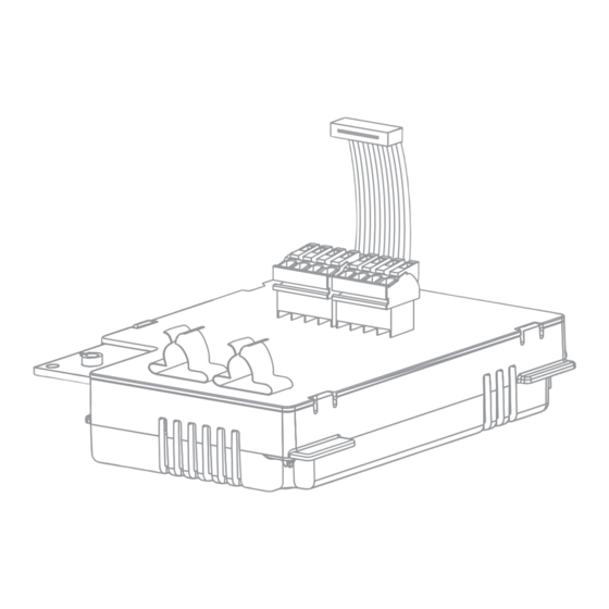
Ribbon cable plug Ribbon Cable Type label 4.2 Type Label The type label clearly identifies the 485 Data Module. The type label is located at the bottom right on the back of the 485 Data Module. Figure 4: Information on the type label... -
Page 10: Cable Gland
Type Device type You will require the information on the type label to use the 485 Data Module safely and when seeking customer support from the SMA Service Line. The type label must remain permanently attached to the 485 Data Module. -
Page 11: Connection
Overview of the connection area Position Designation Flipped up display with screw Cable route to the plugs of the 485 Data Module Inverter enclosure opening for cable gland Mounting position of the 485 Data Module in the inverter Installation Manual... -
Page 12: Installing The 485 Data Module In The Inverter
5 Connection SMA Solar Technology AG 5.2 Installing the 485 Data Module in the Inverter Danger to life due to electric shock when opening the inverter Death or serious injuries • Disconnect the inverter from all voltage sources on the AC and DC sides and open it (see the inverter installation manual). - Page 13 6. Insert the 485 Data Module and push the ribbon cable upwards behind the display. The key on the top edge of the 485 Data Module must fit into the hole in the plastic retainer in the inverter. 7. 485 Data Module hand-tight using a hexagon socket screw (AF 3, torque: 1.5 Nm).
-
Page 14: Connecting The 485 Data Module
• Lay the RS485 communication cables using suitable fastening material and with a minimum clearance of 50 mm to the AC cables. Procedure: To connect the 485 Data Module, perform the following work steps in the prescribed sequence. The exact procedure is described in the following sections. • Prepare the cable •... - Page 15 SMA Solar Technology AG 5 Connection Connecting the Cable to the 485 Data Module 1. Flip the display up until it snaps into place. 2. Unscrew the swivel nut of the cable gland on the inverter. 3. Press the seal out of the cable gland from the inside.
- Page 16 5 Connection SMA Solar Technology AG 9. Remove or connect the terminator: • If two cables are connected, open the spring clamp terminals of the plug with the connected terminator and remove the terminator. • If one cable is connected, the terminator in the unused plug must be connected in terminals 2 and 7.
- Page 17 SMA Solar Technology AG 5 Connection ☑ One cable is connected to the 485 data module. 14. Fasten the swivel nut on the cable gland hand-tight. This relieves pull strains on the cables. 15. Flip the display down and fasten the screw of the display hand-tight.
-
Page 18: Decommissioning
9. Pull the cable gland and cables out of the inverter. 10. Release the screw of the 485 Data Module and remove the 485 Data Module. 11. Close the spring clamp terminals of the plugs on the 485 Data Module. -
Page 19: Packaging The 485 Data Module For Shipping
6 Decommissioning 6.2 Packaging the 485 Data Module for Shipping • Pack the 485 Data Module. To do so, use the original packaging or packaging that is suitable for the weight and size of the 485 Data Module. 6.3 Disposing of the 485 Data Module •... -
Page 20: Troubleshooting
Problem Cause and corrective measures The emergency channel list "Emergncy" The 485 Data Module has been installed in an inverter or "EmgncyXX" is displayed in the without first disconnecting the inverter on the AC and DC communication product (e. g. Sunny sides. -
Page 21: Technical Data
SMA Solar Technology AG 8 Technical Data 8 Technical Data Mechanical Data Width x height x depth 73 mm x 88 mm x 34 mm Weight 71 g Communication Communication interface RS485 Maximum cable length 1200 m Terminals Type of plug... -
Page 22: Contact
SMA Solar Technology AG 9 Contact If you have technical problems with our products, please contact the SMA Service Line. We require the following information in order to provide you with the necessary assistance: • Type, serial number, and firmware version of the inverter •... - Page 23 +562 2820 2101 08600SUNNY (08600 78669) Perú International: +27 (0)21 826 0600 Australia SMA Australia Pty Ltd. Other countries International SMA Service Line Sydney Niestetal 00800 SMA SERVICE Toll free for Australia: (+800 762 7378423) 1800 SMA AUS (1800 762 287)
- Page 24 SMA Solar Technology www.SMA-Solar.com...
Need help?
Do you have a question about the 485 Data Module and is the answer not in the manual?
Questions and answers