Advertisement
Table of Contents
Advertisement
Table of Contents

Related Manuals for Sunstream SunLift SLX 5010


Summary of Contents for Sunstream SunLift SLX 5010
- Page 1 SLX 6512 SLX 8012 SLX 9012 SLX 10014 SLX 12016 ASSEMBLY , INSTALLATION & USE MANUAL SLX 10014 SHOWN READ CAREFULLY, KEEP THESE INSTRUCTIONS COPYRIGHT SUNSTREAM CORPORATION 2020 - PATENTS PENDING - ALL RIGHTS RESERVED PART NO. 690963 REV: A-01...
-
Page 2: Troubleshooting
Table of Contents Overview of SunLifts Part Lists Sunlift Accessories Assembly of Sunlift 10-23 Connecting to Power Pack Completing Assembly Installation 26-27 Use and Maintenance Remote Control 29-30 Troubleshooting Safety 32-34 Warranty 35-36 PART NO. 690963 REV: A-01... -
Page 3: Overview Of Components
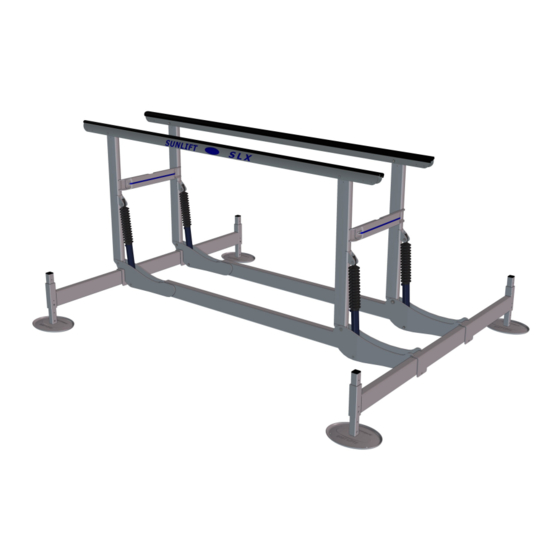
Overview Of Components Common 2 cylinder SLX SLX5010, SLX6512, SLX8012 & SLX9012 Forward H-Frame, Left Bunk Rear H-Frame, Left Cross Beam Cylinder Boot Diagonal (SLX9012 only) Side Beam Bridge Tube Hydraulic Cylinder Foot Pad SLX9012 SHOWN PART NO. 690963 REV: A-01... - Page 4 Overview Of Components Common 4 cylinder SLX SLX10014 & SLX12016 Forward H-Frame, Right Bunk Rear H-Frame, Right Bridge Tube Boot Hydraulic Cylinder Side Beam Cross Beam Foot Pad SLX10014 SHOWN PART NO. 690963 REV: A-01...
-
Page 5: Parts List
Parts List AVAILABLE LEGS 2 FT (24") SA-LR2 4 FT (48") SA-LR4 6 FT (72") SA-LR6 8 FT (96") SA-LR8 12 FT (144") SA-LR12 16 FT (192") SA-LR16 24 FT (288") SA-LR24 SLX 5010 PART PART NUMBER SIDE BEAM 952454 CROSS BEAM 952452 BUNK... - Page 6 Parts List SLX 6512 PART PART NUMBER SIDE BEAM 952453 CROSS BEAM 952452 BUNK 942484 BRIDGE TUBE 413058 FWD H-FRAME, RIGHT 952428 FWD H-FRAME, LEFT 952427 REAR H-FRAME, RIGHT 952430 REAR H-FRAME, LEFT 952429 FOOT PAD 433111 *SEE CHART ON PAGE 5 HARDWARE KIT 912480 CYLINDER...
- Page 7 Parts List SLX 10014 PART PART NUMBER SIDE BEAM 952422 CROSS BEAM 952426 BUNK 942485 BRIDGE TUBE 413058 FWD H-FRAME, RIGHT 952432 FWD H-FRAME, LEFT 952431 REAR H-FRAME, RIGHT 952478 REAR H-FRAME, LEFT 952477 FOOT PAD 433111 *SEE CHART ON PAGE 5 HARDWARE KIT 912482 CYLINDER...
-
Page 8: Popular Accessories
Popular Accessories GUIDE-ONS ACTS AS A VISUAL GUIDE FOR EASIER BOAT LOADING. (ONE PAIR) PART # SA-GOA5 PART # SA-GOA6 BOW STOP ACTS AS A BUMP STOP FOR YOUR BOATS BOW SO IT ISN’T LOADED TO FAR FOR- WARD PART # SA-BS1 ADJUSTABLE RANGE INSERTS RAISES H-FRAME/BUNK HEIGHT FOR HIGHER WATER LEVEL FLUCTUATION AREAS. -
Page 9: Other Accessories
5ft Hydraulic Hose extension (pair): SA-HX51 15ft Hydraulic Hose extension (pair): SA-HX151 30ft Hydraulic Hose extension (pair): SA-HX301 Guide-on Pads (36” black): SA-GP36B Translating Load Guides: SA-LGT2 Contact your local dealer or Sunstream for more information regarding accessories. PART NO. 690963 REV: A-01... - Page 10 Assembly If you have any questions during the assembly process, please call your local dealer or Sunstream Before beginning assembly, find a nice flat area with room to work to set up your lift. Read ahead to the Installation Procedure to determine the best location to start. Assembly will require the follow- ing tools: 1.
- Page 11 Step 1 Legs and feet NOTE: I NSTALL CAP AFTER LEG IS TRIMMED TO FINAL HEIGHT. LARGER GAP UP NUT, BRONZE .375-16 PART: 121199 HEX HEAD BOLT, .375-16 X 3” PART: 11-061200-16 SMALLER GAP DOWN FOOT PAD LEG CAP PART: 19-000000-77 LEGS 2 FT (24") SA-LR2...
-
Page 12: Rubber Washer
Step 2 Legs and crossbeam SET SCREW & RUBBER WASHER (INSERT LAST, 4 PLACES) LEG BOLT RUBBER WASHER NUT, BRONZE .375-16 PART: 131196 PART: 121199 HEX HEAD BOLT, .375-16 X .50” HEX HEAD BOLT, .375-16 X 4” PART: 11-060202-44 PART: 11-061600-18 PART NO. - Page 13 Step 2 continued Optional direct foot install for shallow water NUT, BRONZE .375-16 PART: 121199 HEX HEAD BOLT, .375-16 X 4” PART: 11-061600-18 PART NO. 690963 REV: A-01...
- Page 14 Step 3 Sidebeams and Crossbeams NUT, BRONZE .375-16 PART: 121199 HEX HEAD BOLT, .375-16 X 4.5” PART: 11-061800-19 PART NO. 690963 REV: A-01...
- Page 15 Step 3 continued CENTER LINE WIDTH (inside to inside of saddles) 29.0” Narrow 33.0” Standard 37.0” Wide 41.0” Extra Wide NOTE: For easier adjusting of side beams, apply grease on top and inside of saddles. PART NO. 690963 REV: A-01...
- Page 16 Step 4 H-Frame width WIDTH (between uprights) 33.6” Narrow 37.6” Standard 41.6” Wide 45.6” Extra Wide NOTE: H-frames pre-set to Standard width. NUT, BRONZE .375-16 HEX HEAD BOLT, .375-16 X 2.5” PART: 121198 PART: 11-061001-92 PART NO. 690963 REV: A-01...
- Page 17 Step 5 Rear H-Frame APPLY MARINE GREASE TO ALL PINS HEADED PIN 1.25” X 5” 1.25” STAINLESS WASHER COTTER PIN 2” PART: 141189 PART: 131195 PART: 141197 PART NO. 690963 REV: A-01...
- Page 18 Step 6 Forward H-Frame (2 Cylinder Lift) APPLY MARINE GREASE TO ALL PINS HEADED PIN .75” X 4.88” COTTER PIN 1.5” .75” STAINLESS WASHER PART: 141190 PART: 14-000001-44 PART: 13-120000-59 PART NO. 690963 REV: A-01...
- Page 19 Step 6 continued (4 Cylinder Lift) APPLY MARINE GREASE TO ALL PINS .75” STAINLESS WASHER HEADED PIN .75” X 4.88” COTTER PIN 1.5” PART: 13-120000-59 PART: 141190 PART: 14-000001-44 PART NO. 690963 REV: A-01...
- Page 20 Step 7 .75” STAINLESS WASHER PART: 13-120000-59 HEADED PIN .75” X 4.88” PART: 141190 HEADED PIN .75” X 3.19” COTTER PIN 1.5” PART: 141191 PART: 14-000001-44 (SHORTER) 3.19” PIN ON ROD OF CYLINDER (LONGER) 4.88” PIN ON BARREL OF CYLINDER NOTE: CY LI NDER SH OW N WITHOUT BOOT FOR CLARITY APPLY MARINE GREASE TO ALL PINS...
-
Page 21: Hose Routing
Step 7 continued HOSE ROUTING 2 CYLINDER LIFTS: HOSES TO BE ROUT- ED TO DOCK SIDE UNDER CROSS BEAM, SIDE BEAM AND H-FRAME TO AVOID ANY POSSIBLE PINCH POINTS FRONT OF LIFT SIDE BEAM TO POWER PACK BACK OF LIFT CROSS BEAM PART NO. - Page 22 Step 7 continued HOSE ROUTING 4 CYLINDER LIFTS: HOSES TO BE ROUT- ED TO THE FRONT OF LIFT. HOSES TO BE ROUTED UNDERNEATH CROSS BEAM, SIDE BEAM AND H-FRAMES TO AVOID ANY POSSI- BLE PINCH POINTS. FRONT OF LIFT TO POWER PACK SIDE BEAM BACK OF LIFT CROSS BEAM...
- Page 23 Step 8 APPLY MARINE GREASE TO ALL PINS COTTER PIN 1.5” HEADED PIN .75” X 4.22” .75” STAINLESS WASHER PART: 14-000001-44 PART: 141192 PART: 13-120000-59 PART NO. 690963 REV: A-01...
- Page 24 Step 9 CONNECTING THE QD’S (QUICK DISCONNECTS) NOTE: FOR P ROP ER CONNEC- TION, QD’S MUST BE TIGHTENED WITH A WRENCH UNTIL THEY BOTTOM OUT. BE CAUTIOUS NOT TO CROSS-THREAD QD’S. BATTERY RC BOX RESERVOIR PUMP PART NO. 690963 REV: A-01...
- Page 25 It is imperative that you replace the zinc on your lift regularly. Because many external factors affect the rate at which a zinc deteriorates, Sunstream recommends that you check its condition frequently, and change the zinc every six months or more often if needed. Zincs on lifts in coastal areas near the ocean deteriorate more rapidly and need to be changed more frequently.
-
Page 26: Installation
Installation The Maximum Capacity for the Lift should be listed on the lift itself - if it is not, call Sunstream immediately to determine your lifts capacity. Operating the Lift with a greater amount of total weight may cause the lift and boat to become unstable and/or capsize, possibly causing property damage and/or and severe injury or death to individuals situated nearby. - Page 27 Installation LEVELING AND FINAL POSITION A. Leveling the Sun Lift: Once you have adjusted the lift in its final position, you must now ensure that it is level. To do this, use a suitable measuring device and measure the distance from the top of the Cross Beam to the water surface. The distance at each of the four cor- ners of the lift should be within 2 inches of each other.
- Page 28 Use and Maintenance Sunstream recommends an annual inspection of the SunLift by an authorized Sunstream Dealer or other qualified person. For storage and off-season suggestions be sure to prevent rainw ater from accum ulating in your boat if you plan to leave it on the lift for long term storage.
-
Page 29: Battery Monitoring
RC401 Remote Control instructions RC401 Basic Instructions Note: Exit ‘PROGRAM MODE’ to operate the lift. Add Transmitter: P ress and release the R ed ‘Program’ button once so the ‘Add Trans- mitter’ light flashes, then press ‘Up’ on the transmitter three (3) times. Clear Memory: P ress and hold ‘PROGRAM’... -
Page 30: Security Mode
Security Mode The keypad can be locked to prevent tampering with the lift. The transmitter still functions in Security Mode. The factory setting of the security code is 1223, but this may be changed. The keypad has only numbers 1, 2 and 3 which are selected by pressing ‘Power’, ‘Up’ or ‘Down’... - Page 31 Troubleshooting the SunLift SLX Problem Possible Solution(s) Lift does not operate with manual switch on RC box Check power on RC box is on Check battery voltage Check all wires are connected to Solenoids on pump Lift does not operate with key fob transmitter buttons. ...
-
Page 32: Disclaimer Of Liability
Sunstream Dealer and are not a reasonably skilled me- chanic, please contact Sunstream so that we can refer you to a local dealer who can skillfully and safely perform the assembly and installation of your Sun- stream boat lift. -
Page 33: Important Safety Instructions
Sun Lift. The Maximum Capacity for the Lift should be listed on the lift itself - if it is not, call Sunstream immediately to determine your lifts capacity. Operating the Lift with a greater amount of total weight may cause the lift and boat to become unstable and/or capsize, possibly causing property damage and/or and severe injury or death to individuals situated nearby. - Page 34 Safety It is safest to leave the boat in the over-center position. Be sure the Sun Lift remains level at all four corners. Out of level installations may cause lift failure and personal injury. All four corners must be within 2” of each other. If a Sun Lift is located near an area where swimmers are prone to diving into the water (such as off of a boathouse), make sure they are aware of the location of the Sun Lift when boat is not present, and lift is hidden under water.
-
Page 35: Warranty
Warranty WARRANTY: Sunstream Corporation (“Company”) warrants its Products for non-commercial and/or non- ® governmental use for a period of three (3)* years, in both fresh and salt water, to the original Purchaser (“Purchaser”) against manufacturing defects in all Product materials and workmanship beginning from... - Page 36 Purchaser must find the source of this current and stop it, or change zincs more frequently. Sunstream Corporation ® 22149 68...
Need help?
Do you have a question about the SunLift SLX 5010 and is the answer not in the manual?
Questions and answers