Table of Contents
Advertisement
Quick Links
Advertisement
Table of Contents

Related Manuals for SevenStar D08-2F


Summary of Contents for SevenStar D08-2F
- Page 1 D08-2F, D08-3F, D08-4F Flow Readout Boxes INSTRUCTION MANUAL Version July,2020...
- Page 2 SEVENSTAR may not be responsible. If you require any additional information or assistant of Sevenstar D08 series Flow Readout Boxes. Please feel free to contact your local Sevenstar Sales Agent or Sevenstar Customer Service at: (8610)- 6436 2925.
-
Page 3: Table Of Contents
CONTENTS APPLICATIONS & FEATURES......Preparation............SPECIFICATIONS..........6.1.1 Control Buttons..........FRONTAL & BACK OPERATION PANELS..6.1.2 Power Lead Connection........STRUCTURE INSTRUCTION......6.1.3 Control Line Connection......... ±15V Power Supply..........Operation Method..........+5.00V Nominal Power Supply......6.2.1 Turn On............Displayer.............. 6.2.2 Zero Adjustment..........Valve Controller........... -
Page 4: Applications & Features
D07 series MFC or MFM without any change. And it can also be used for other models of MFC or MFM. With standard desk-style section bar chassis, D08-2F, 3F, 4F Flow Readout box can control 2, 3 or 4 MFCs (or MFMs). And each channels have the independent displays and control potentiometers. -
Page 5: Frontal & Back Operation Panels
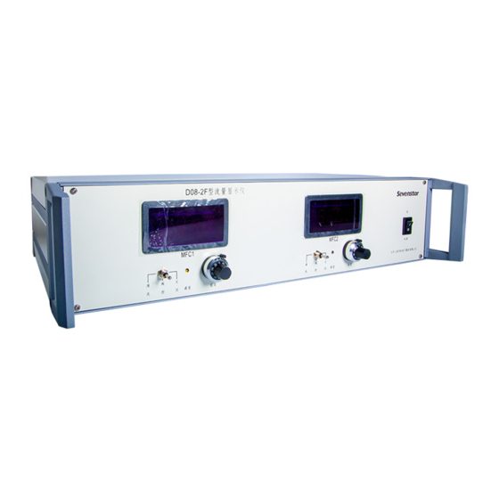
Range Adjustment Radix Point Set AC Power MFC D Connector Fuse EXT Control Connector INT & EXT Setting Selection Figure 1. Frontal & Back Operation Panels of D08-2F Figure 2. Frontal & Back Operation Panels of D08-3F Page 2 of 12... -
Page 6: Structure Instruction
220VAC / 110VAC Figure 3. Frontal & Back Operation Panels of D08-4F STRUCTURE INSTRUCTION 4.1 ±15V Power Supply Composed by three-terminal integrated stabilized modules, ±15V power supply with the simple connection, high stability and reliability are available as well as over-heat and over-load protections in the integrated stabilized electric circuit. -
Page 7: Valve Controller
4.11 MFC “D” Connector 15pin D connector is used for connection with the MFC/MFM. Every connector (channel) can only be connected to one MFC. Thus, two channel for D08-2F, three channel for D08-3F, and four channel for D08-4F. 4.12 External Control Connector The 0-5V voltage can be used for external control signal Please refer table 3 for connection. -
Page 8: Nameplate
Nameplate indicates the actual situation of each MFC (or MFM) channel when flow readout box connected with MFC (or MFM), for example the full scales and flow units. 5. INSTALLATION & CONNECTION 5.1 Dimension ( Figure 4.) D08-2D/ZM 流量显示仪 通 MFC1 MFC2 电源... - Page 9 Controller Signal Functions External Zero Signals Instruction of Table 2: ① Necessary signals:±15V, Power Common, Set, Flow Power Common Output and Signal Common. These signals must be connected correctly. ② “Valve Drive” and “ External Zero Adjustment” Valve Drive signals are only for D07 series MFC products. For Signal Common other MFC products, please do NOT connect Flow Readout...
-
Page 10: External Control Connection
For External Control Connection, please refer to Table 3. PC or other external control equipments can control the MFC by external control connector. Table 3. External Control Connection c. D08-4F b. D08-3F a. D08-2F External Control Signal External Control Signal External Control Signal Functions... -
Page 11: Operation Procedure
Signals Instruction of Table 3: a. The voltages between External Set Ⅰ~Ⅳ and signal common will be used for setting the 1~4 channel MFC respectively. If external potentiometer is used for setting, a 3.3K potentiometer can be connected with “+5.00V” and “ Signal common”, and its tap can be connected with “External Set”. -
Page 12: Power Lead Connection
AC power should be shut off after using. 7. PARAMETER SETTING Please select the appropriate flow unit and range for the MFC/MFM. If necessary, the user can change flow unit and range by “radix point”, “Unit set” and “range adjustment” for D08-2F/3F/4F. Page 9 of 12... -
Page 13: Range Selection
7.1 Range Selection High accuracy will be acquired by the appropriate range and radix. Normally the full range should be 1,000. For example, if the full scale of MFC/MFM is 30SCCM or 30SLM, the full scale range of the box should be 30.0 (one decimal place) instead of 30. -
Page 14: Substitution
8.3 Substitution If the Flow Readout Box is used for other model MFC (or MFM), please make sure the capability of power supply and the correct connections firstly. Especially, please be very careful for the valve control function and connections because it is quite different according to the different models. -
Page 15: Order Form
9.2 Order form D08- [t] - [p] - [s] [t] – Type 2F/3F/4F scale code 5sccm 10sccm 20sccm [p] – Power supply -[ ] ~220VAC±10% 50Hz 30sccm include ~85-265VAC wide voltage input 50sccm -[D] ~110VAC±10% 60Hz 100sccm 200sccm [s] – Special request 300sccm -[ ] percentage display (%FS) for each channel,... - Page 16 Beijing Sevenstar Flow Co.,Ltd. D08 Series Flow Readout Boxes Beijing Sevenstar Flow Co., Ltd. Address: No.8 Wenchang Avenue Beijing Economic-Technological Development Area Post code: 100176 (+86)10-56178088 Tel: (+86)10-56178099 Fax: Homepage: www.mfcsevenstar.cn E-Mail: mfcsales@sevenstar.com.cn Room 511, Building 29, No.368 Zhangjiang Road, Pudong...
Need help?
Do you have a question about the D08-2F and is the answer not in the manual?
Questions and answers