
Related Manuals for SevenStar D07–60B


Summary of Contents for SevenStar D07–60B
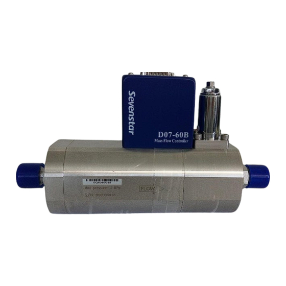
- Page 1 D07 – 60B Mass Flow controller D07-60BM Mass Flow Meter INSTRUCTION MANUAL 2017.03...
- Page 2 A NOTE TO OUR CUSTOMERS The Sevenstar D07 series Mass Flow Meter/Controller you have just received is of the leading quality available. It includes excellent high degree of accuracy and repeatability, in addition to the variety of operation pressure available.
-
Page 3: Table Of Contents
目 录 1. APPLICATION & FEATURES……………. 5.2.2 Zero Test and Adjustment………………….. 2. SPECIFICATION………………………….. 5.2.3 Gas Supply…………………………………. 3. STRUCTURE & PRINCIPLE……………... 5.2.4 Shut Off……………………………………. 3.1 Structure……………………………………. 6. CAUTION…………………………………… 6.1 Medium Forbidden …………………………... 3.2 Operation Principle………………………… 4. INSTALLATION & CONNECTION …….. 6.2 Corrosive Gas ……………………………….. 6.3 Valves Dynamic Sealing …………………….. -
Page 4: Application & Features
Operating Instruction 1. APPLICATION & FEATURES Mass Flow Meter (MFM) accurately measures mass flow rates, Mass Flow Controller (MFC) accurately measures and controls mass flow rates despites gas volume fluctuated due to pressure or temperature changes. They are widely applied in the fields as: semiconductor and IC fabrication, special materials science, chemical industry, petrolic industry, pharmaceutical industry, environmental protecting and vacuum system researching, etc. -
Page 5: Specification
Tem — 273.15K ( 0 º C ); Standard Situation: Air Pressure — 101325 Pa (760mm Hg) For Sevenstar MFC/MFM, the unit of SCCM is identical to “mL/min, 0 º C ,1atm”, and the unit of SLM Page 2 of 26... -
Page 6: Structure & Principle
is identical to “L/min, 0 º C ,1atm”. F.S. : Full Scale 3. STRUCTURE & OPERATION PRINCIPLE 3.1 Structure The MFM consists of flow sensor, flow-splitter bypass and flow amplifying circuit. If add Control valves and PID control circuit to MFM will compose a MFC. 3.2 Operation Principle According to the Capillary Heat Transfer Temperature Difference Calorimetry Theory, the flow sensor measures the mass flow without pressure compensation. - Page 7 +5.00V FLOW READOUT BOX 100.0 (0 ~ +5.00V) Readout Setpoint +15V (0 ~ +5.00V) Output Power Com. Power ~220V Signal Com. -15V MASS FLOW Comparator CONTROLLER Amplifier +15V Valve AUTO Drive Override PURGE -15V Sensor Valve INLET OUTLET Bypass Figure2. Principle of MFC The outputting flow testing signal from MFC is a direct ratio with the flow through the channels, flow outputting signal is 0~5VDC.
-
Page 8: Installation & Connection
Operation control could accomplish by Flow Readout Box. When set point is turned on the “INT”, flow rate will be under controlled by the presetting potentiometer; when setpoint is turned on the “EXT”, flow rate will be controlled by set signal which is supplied by users. There are three valves control switches on the panel of D08 series Flow Readout Box: CLOSE, PURGE and AUTO. - Page 9 Flange DIN DN15- PN40 DIN DN20- PN40 DIN DN25- PN40 Figure 3b. Dimension of D07-60B MFC With Flange Page 6 of 26...
- Page 10 Figure 3c. Dimension of D07-60BM MFM With 1/2″/φ10 Compression Fitting Fitting Page 7 of 26...
- Page 11 Figure 3d. Dimension of D07-60BM MFC With Flange Attention: The height of figure 3a、3b、3c、3d are height without electric connectors of cable. It should be added around 50mm more after adding the electric connector. Page 8 of 26...
-
Page 12: Fittings
4.2 Fittings Four models of external diameters connectors could be provided: Table2. Connectors & Dimensions of D07-60B、D07-60BM MFC/MFM Compression Fitting Note Model Φ10 (≤1000SLM) 1/2" (300SLM) Mark"○" means could be ○ ○ 1 D07—60B selected, but each model only could be selected one ○... -
Page 13: Electrical Interfacing
which will affect its airproof function. Electrical Interfacing MFC could begin operating after it was well connected with professional cable and corresponding Flow Readout Box. The electrical interfacings of each MFC and MFM are showing as following figures (Figure 5 ~ Figure 6). Set(0-5VDC) +15V Valve test point... - Page 14 a. Connection through Flow Readout Box with PC or other external signal. (Figure 7) 4~20mA Output I A/D In Signal common Signal common Connection D/A Out 4~20mA MFC or Signal common Cable Valve Off (ATTENTION: COMPUTER No “Valve OFF/ON” Readout Box Or PLC and “Set”...
- Page 15 b. PC Directly Connections (Figure 8) 0~+5V Flow Signal Output A/D In Signal common Signal common PC or PLC 0~+5.00 D/A Out Signal common MFC or MFM No “Valve drive” (ATTENTION: and “Set” in MFM ) Auto Valve drive +15V +15V Purge common...
-
Page 16: Zero Adjustment
4.5 Zero Adjustment It could be zero adjusted in case of zero excursions while the first time operates or a long period operating. Users could adjust Zero Potentiometer from side face (showing in figure 9) or adjust it while removed its overall. Please note it should be sure that gas flow tube could not be open while zero adjustment (or shutoff the valves);... -
Page 17: Operation Instructions
There is another external zero adjustment function, while MFC connected with our new zero adjustment functional D08 Flow Readout Box, it could be achieved by zero potentiometer of display panel. The important is the ranges of external zero adjustment is narrow, when there is big zero excursion happened, it should be better adjust zero from zero potentiometer of MFC. -
Page 18: Purge
be warming up around 15 minutes in case valves shut off and gas flow cut off, after stable zero movement, normal operation could begin. If there is big zero excursion, please see the reference 4.5, in the case of non-gas flow, it’s better adjust zero by zero potentiometer. -
Page 19: Mfm Operation
5.2 MFM Operation 5.2.1 Start Up Please warm up for 15 minutes by power supply before MFM operating. 5.2.2 Zero Testing and Adjustment Please check up zero point of MFM after its warming up (especially for the first time operating), it could have reference in 4.5, without gas supplying, which could adjust zero by zero potentiometer. -
Page 20: Valves Operating
perform that kind of function. Users should better have that plug valve by themselves. Especially when users operate with caustic gas, general speaking, it should separately add one cut-off valve of MFC inlet and outlet to protect operating security. After a long period operating, if the leakage rate of MFC valve outlet is not beyond 2% F.S., it is the standard situation. -
Page 21: D07-60B,60Bm Ordering Code
D07-60B,60BM Ordering Code D07-[t] [g,g,g] [r,r,r,r] [f,f] – Type Number - [60B ] MFC - [60BM] MFM [g,g,g] – Please consult SEMI52-0302 For Example: -[ 013 ] N -[ 007 ] H -[ 000 ] Mixture gases (please consult [d] for detail) [r,r,r,r] –... - Page 22 D07-[t] [g,g,g] [r,r,r,r] [f,f] Seal Materials – -[ V ] Viton -[ N ] Neoprene – Mounting Position -[ H ] Horizontal -[ E ] HESD(Horizontal Edge Side Down) -[ U ] Vertical Inlet Up -[ D ] Vertical Inlet Down Description –...
- Page 23 For Example: D07-60B0131K0LPPVHS D07-60B 013 1000L PP D07-60B MFC Type Number: Gas:N 1000SLM Flow Range Full Scale: Inlet and Outlet Fittings: Compression Fitting 1/2" Seal Materials:Viton Mounting Position:Horizontal Customer Special Requirements: For Example: The letters on cover and Tag: in English;Differential Pressure:(0.30~0.60) MPa; Customer Special fittings(According to drawing) ;Customer Special Calibration Temperature:40℃.
-
Page 24: Troubleshooting
7. TROUBLESHOOTING Table 3. Failure Handling FAILURE CAUSE TREATMENT There is no gas flow 1.1 Gas flow is shutting off, no gas Check the gas sourcing and make it open after turn on. inputting 1.2 Valve control switch is shutoff Turn the switch to CONTROL or PURGE Check potentiometer or “In/Out”... - Page 25 Continue To Table 3. Failure Handling FAILURE CAUSE TREATMENT Fluctuant flow rate Inlet pressure is too low or Heighten inlet pressure instable 5.2. High internal gas resistance Lessen internal resistance (The heavy gas flow should have big valve open, widen tube to parallel connecting gas bottles to improve gas supply capacity.) 5.3 Circuit or valve failure...
-
Page 26: Warranty & Service
Buyers undertake to check and inspect the goods and to notify SevenStar of shipment incidents by fax, phone or e-mail as soon as possible after receipting the goods. -
Page 27: Appendix
9. APPENDIX 9.1 Mass Flow Conversion Factors Table 4. Conversion Factors ρ GAS CODE HEAT Factors ( Cal/g ℃) (SEMIE52-0302) (g/l 0℃) 0.2400 1.2930 1.006 0.1250 1.7837 1.415 0.1168 3.4780 0.673 0.0647 11.1800 0.378 0.1217 5.2270 0.430 0.1779 3.0250 0.508 0.5020 1.2350 0.441... - Page 28 Continue To Table 4. Conversion Factors ρ GAS CODE HEAT Factors ( Cal/g ℃) (SEMIE52-0302) (g/l 0℃) 0.1405 3.4180 0.569 3.4224 0.0899 1.010 0.0861 3.6100 1.000 0.1911 1.6270 1.000 0.3482 0.8930 1.000 0.0545 5.707 0.999 0.2278 1.5200 0.844 1.2418 0.1786 1.415 0.0593 3.7390...
-
Page 29: Conversion Factors Introduction
9.2 Conversion Factors Instruction MFC and MFM are standard calibrated by N while it’s out of factory. Other gas calibrations can be approximated by converting of conversion factors of our instruction. While using other gas operating: One single gas: The conversion factors could find out in the users specification instruction. A mixture of two or more gases: Assume there is “n”... - Page 30 Beijing Sevenstar Flow Co., Ltd. D07 Series Mass Flow Controller Beijing Sevenstar Flow Co., Ltd. Address: No.1 Jiuxianqiao East Rd., Chaoyang District, Beijing, China P.O.BOX 3#741, Beijing, China Post code: 100015 Tel: (+86)-10-64361831 ext. 8527 Fax: (+86)-10-64362923 Homepage: www.mfcsevenstar.cn E-Mail: mfcsales@sevenstar.com.cn...
Need help?
Do you have a question about the D07–60B and is the answer not in the manual?
Questions and answers