
Related Manuals for CHESTER Crusader


Summary of Contents for CHESTER Crusader
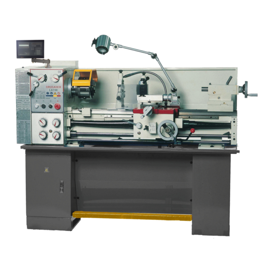
- Page 1 Crusader Lathe Operation Manual Chester UK Ltd Clwyd Close Hawarden Industrial Park Hawarden Chester CH5 3PZ Tel: 01244 531631 sales@chestermachinetools.com www.chestermachinetools.com...
-
Page 2: Table Of Contents
Contents Machine Specifications Electrical System Installation Levelling Lubrication Chart Operation Instruments Protection Instruments Troubleshooting Maintenance Parts List and Diagrams... -
Page 3: Machine Specifications
1. Machine Specification The Crusader Lathe has been designed for small to medium sized workpieces and suitable for use in machining workshops, tool rooms, and repair workshops to machine shafts, sleeves and disc shaped workpieces. This machine can also be used to cut imperial, diametric and module pitch threads. -
Page 4: Electrical System
2. Electrical System This machine has been wired as either a 230V Single Phase machine or a 415V 50hz 3 Phase machine. The electrical system in the lathe has been installed and adjusted prior to delivery, as such it should not normally be necessary to open the electrical box. Connect the machine to the power supply making sure that the ground has been correctly wired. - Page 5 Single Phase...
- Page 6 2.2 Wire Chart Three Phase...
- Page 7 Single Phase...
-
Page 8: Installation
2.3 Description Symbol Name Symbol Name Motor Jog Switch End Gear Train Cover Limit Transformer Switch Indicator Light Chuck Guard Limit Switch Work Light Brake Switch Stop Switch Thermal Relay Emergency Stop Button 3. Installation Caution! The machine must be securely and stably fitted. Do not turn, lower or make any sharp movements through shaking, wind force, or any other external movements. -
Page 9: Levelling
any direction. The carriage, tailstock and other sliding parts of the lathe are locked before delivery, do not loosen these until the machine is installed in its final location. Before lifting the machine, confirm that these items are fully locked down to prevent causing an accident in the event they are not locked and move. -
Page 10: Lubrication Chart
Any adjustments at one end of the bed will affect the reading at the other end, the levelling procedure may need to be repeated several times until the bed is level along the length of the guideway. Once any adjustments are complete, carefully tighten the foundation screws, the tension should not change the level of the machine, re-check the levels and make minor adjustments if necessary. - Page 11 9. Operation Instructions 1. Speed Levers and Feed Direction Lever; 2. Headstock Cover; 3. Headstock; 4. Three Jaw Chuck; 5. Gap; 6. Steady Rest; 7. Follow Rest; 8. Tool Post Handle; 9. Tool Post Slide; 10. Tailstock Quill Clamping Lever; 11. Tailstock; 12. Tailstock Clamping Lever;...
- Page 12 limitations of the lathe, the tool and the rigidity of the workpiece. Do not overload the machine by taking too large a cut. As a guide, the following chart gives an idea on the cutting speed, depth and feed rate when cutting metals, when cutting wood, plastic and other non-metals, the cut depth can be increased.
- Page 13 9.2 Spindle Speed The main spindle is capable of 18 speed steps which can be achieved by changing the lever position, the speed can be adjusted as follows: 1. Move the control lever to the middle position to turn off the main motor. 2.
- Page 14 When the control lever is in the middle position, the machine will stop. 9.5 Gearbox Note: To avoid the rotation of the leadscrew, the handle must point to the black dot when feeding. Thread cutting can be completed by operating all four handles as per the thread chart and operating the thread cutting engagement lever down.
- Page 15 b) Longitudinal and Cross Feed Table, Metric Leadscrew...
- Page 16 Thread Table a) Thread Table, Imperial Leadscrew...
- Page 17 b) Thread Table, Metric Leadscrew...
- Page 18 9.6 Carriage The function of the carriage is to securely support the tool post and carry it when moving in both the longitudinal and cross directions. 1. Power Feed When performing external turning facing operations, turn the lever to the black dot on the gear box to engage the feed rod.
- Page 19 successive cuts must be made on number 1 or 3. 1-8 means that the half nut can be engaged on any line. If the half nut is left engaged when cutting the thread then the dial indicator does not need to be used, in this case once each cut has been completed, stop the machine, back the tool off and reverse the spindle back to the start position.
-
Page 20: Troubleshooting
been completed. When correcting the position of the tailstock, use the following procedure: 1. Fit a 305mm ground steel bar between the centres of the headstock and tailstock (Fig 27). 2. Fit a dial indicator to the compound slide and feed along the centre line of the bar using the carriage movement. -
Page 21: Maintenance
5. A small taper is cut when making an external cut between centres. A. The workpiece is not on the same line between the spindle and tailstock – Adjust the tailstock position. B. The movement line of the tool with the carriage is not parallel with the spindle – loose the headstock locking screws and adjust the spindle centre to the required position and lock the headstock into position. - Page 22 4. Annual Maintenance A. Check the level of the machine and adjust if necessary. B. Check the terminals, switches and other electrical components to make sure that they are not loose, replace any damaged components. C. Check the accuracy of the machine using a test piece, adjust the position of the headstock and tailstock if necessary.
- Page 23 Parts List and Drawings Bed Assembly...
- Page 24 Part No. Description CM1224C-01-011 Fixing block JB/T7940.4 Oil cup 6 GB/T70 Screw M8x25 GB/T879 Spring pin 5x25 GB/T77 Screw M8x20 GB/T41 Nut M8 CM1237CHG-01-009 Feeding Rod CM1237CHG-01-013 Switch lever CM1224C-01-011 Switch cover GB/T65 Screw M6x12 CM1224C-01-014 Eccentric block GB/T77 Screw M6x6 GB/T70 Screw M6x12 CM1224C-01-016...
- Page 25 CM1224C-02-005 Motor Seat CM1224C-02-006 Motor Seat CZ1237A-00-001 Pulley Cover GB/T5783 Bolt M12x90 GB/T6172 Nut M12 GB/T96 Washer 12 GB/T70-85 Screw M8x30 GB/T879 Spring Pin 3x5 GB/T1096 Key B5x18 CM1224-06-005 Sleeve CM1224-06-002 GB/T70 Screw M6x12 CM1224-07-004 Spring 1x6x22 GB/T78 Screw M8x12 CM1224-07-003 Cover GB/T308...
- Page 26 Headstock Assembly...
- Page 31 Gearbox Assembly...
- Page 34 Apron Assembly...
- Page 37 Saddle Assembly...
- Page 40 Tool Post Assembly...
- Page 42 Tailstock Assembly...
- Page 44 Follow Rest Assembly...
- Page 45 Steady Rest Assembly...
Need help?
Do you have a question about the Crusader and is the answer not in the manual?
Questions and answers
How do I adjust the slide for taper-turning
To adjust the slide for taper-turning on a CHESTER Crusader:
1. Loosen the screws on the saddle.
2. Rotate the compound slide to the required angle using the graduated dial on the side.
3. Lock the screws to secure the compound slide in place.
4. Use the handwheel at the end of the compound slide to cut the taper.
This answer is automatically generated