
Related Manuals for CHESTER Crusader Deluxe Lathe


Summary of Contents for CHESTER Crusader Deluxe Lathe
- Page 1 Crusader Deluxe Lathe Operation Manual Chester UK Ltd Clwyd Close Hawarden Industrial Park Hawarden Chester CH5 3PZ Tel: 01244 531631 sales@chestermachinetools.com www.chestermachinetools.com...
-
Page 2: Table Of Contents
Contents GENERAL DESCRIPTION OF THE MACHINE General Description Basic Technical Data DESCRIPTION OF THE MAIN UNITS Gearbox Quadrant Feed Box Carriage Group Thread Indicator Tail Stock Rests MACHINE INSTALLATION Unpacking Handling Preparation Mounting, Foundation and Levelling Connection to the Electrical Supply Putting into Operation MACHINE SERVICE Lubrication... -
Page 3: General Description Of The Machine
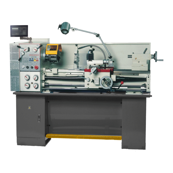
GENERAL DESCRIPTION OF THE MACHINE 1.1 General Data Main Assemblies (see fig 1a) 1. Bed way 13. Lead screw (with guard) 2. Headstock 14. Feed rod 3. Feed box 15. Switch rod 4. Carriage box 16. Tool holder 5. Electrical box 17. -
Page 5: Basic Technical Data
1.2 Basic Technical Data Crusader Deluxe Lathe 300mm Max swing over bed 430mm Max swing over gap 180mm Max swing over cross slide 810mm Distance between centers 38mm Spindle bore 18 steps: 65-1810rpm Range of spindle speed M.T.5 Taper of spindle bore M.T.3... -
Page 6: Description Of The Main Units
2. DESCRIPTION OF THE MAIN UNITS Gear Box The gear box is mounted on the machine corp. The rotation motion to this gear box is transferred though v-belts and belt pulleys from an electric motor mounted on the guide way. Quadrant The quadrant is designed to transfer the motion from the gear box to the feed box through the change gears. -
Page 7: Thread Indicator
The top slide on which the four position tool holder is mounted, can be shifted only by hand in the direction of the cross piece. Thus you may obtain longitudinal, cross and combined feed for the cutting tool. Thread Indicator This device is mounted to the carriage box (disengaged to the driving screw) for getting into the thread pitch. -
Page 8: Machine Installation
3. MACHINE INSTALLATION Unpacking After the machine has been unpacked, check carefully its general condition as well as the condition of all the accessories. Handling The unpacked machine shall be moved only by the help of a suitable crane. Before passing the ropes over the specified places, see fig 2, pull out the tail stock and carriage and fix them in the rear hand position so that when lifting the machine you will obtain the required balance. -
Page 9: Connection To The Electrical Supply
leveling bolts. Connection to the Electrical Supply Check that the data on the electrical panel scheme (voltage and frequency of the supply source) correspond to the power supply available. The controlling level should remain in the middle and also press the power switch down to keep the machine switched off. -
Page 11: Machine Service
4. MACHINE SERVICE Lubricant The trouble-free operation of the lathe depends on careful servicing, especially the regular lubrication of all machine operating parts with the recommended lubricants, see fig 3a, 3b and 3c. The headstock is lubricated by the splashing of oil. The oil may be poured into headstock after the removal of the cap (1) from the oil vent with the oil filler located in the headstock cover. -
Page 12: Recommended Lubricants
Recommended Lubricants Assembly Lubricating Lubricating Lubricant Lubricating point Method Interval Gears and Oil replacement: bearing, 1st time - after Spindle fron 10 days of bearing, operation, 2nd Oil bath - by Machine Headstock Spindle rear time - after 20 splashing bearing, Belt days of pulley bearing... -
Page 13: Machine Operation
5. MACHINE OPERATION Putting into Operation After performing the previous instruction, the machine is ready for operation, the connection to the electric supply is effected by the help of the main interrupter. Turning on the control lamp shows that the machine is connected to the power supply. -
Page 15: Fretted Parts
Adjust the nut gap on the carriage, see fig 7. Rotate the nut (1) to the satisfied saddle motion and required travel. Chuck and faceplate mounting, see fig 8. The connection between the spindle and the chuck or faceplate is made by a D- Cam lock structure. -
Page 17: Mechanisms Adjustment
6. MECHANISMS ADJUSTMENT After a period of time, some of the mechanisms will require readjustment because of the effect of wear and tear on the friction surfaces. The adjustment and setting of the different mechanisms shall be effected after each repair. It is recommended that these adjustments are performed by a qualified specialist. -
Page 18: Machine Care And Maintenance
8. MACHINE CARE AND MAINTENANCE Lathes are a highly accurate machine tool designed to operate around the clock is properly operated and maintained. Lathes must be lubricated and checked for adjustment before operation. Improper lubrication or loose nuts and bolts can cause excessive wear and dangerous operating conditions. -
Page 19: Transmission System & Parts
9. Transmission System & Parts No. of Parts teeth Modulus Pressure Parts Kinds Material Notes of pitch angle thread Gear 20° 2013 Gear 20° 2018 Gear 20° 2019 Gear 20° 2021 Gear 20° 2020 Gear 20° 2022 Gear 20° 2016 Gear 20°... - Page 20 Single ZQSn6- Halfnut 20° Thread Single Worm 20° Thread Worm ZQSn6- 20° 4017 Gear Gear 20° 4030 ZQSn6- Gear 20° 4029 Gear 20° 4014 Left Single 10TPL or ZQSn6- Hand Thread Thread Single 10TPL or Screw Thread Gear 20° 4019 Gear 20°...
-
Page 22: Bearing Distribution
BEARING DISTRIBUTION 60104 20x42x12 Ball Bearing Single Row Single Row Ball Bearing with 60105 25x47x12 Shield Single Row Ball Bearing with 20x52x15 Shield 20x42x12 Single Row Ball Bearing Headstock 25x17x12 Single Row Ball Bearing 20x47x14 Single Row Ball Bearing Single Row Taper Roller D7211 55x100x22 bearing... - Page 23 PARTS DRAWING & PARTS LIST CONTENTS 1. Bed Assembly 2. Head Stock 3. Gear Box 4. Gear Box I 5. Gear Box II 6. Gear Box III 7. Apron 8. Compound Rest 9. Saddle 10. Tail Stock 11. Change Gear 12.
Need help?
Do you have a question about the Crusader Deluxe Lathe and is the answer not in the manual?
Questions and answers