
Subscribe to Our Youtube Channel
Related Manuals for CHESTER Craftsman


Summary of Contents for CHESTER Craftsman
- Page 1 Craftsman Belt Drive Lathe Instruction Manual Chester UK Ltd Clwyd Close, Hawarden Industrial Pk Hawarden, Nr Chester Flintshire. CH5 3PZ Tel: 01244 531631 Email: sales@chesteruk.net www.chesteruk.net...
-
Page 2: Table Of Contents
20 k. Cutting Fluid / Lubric. 21 l. Screw Cutting 22 7. Conclusion 23 8. Parts a. Bed Assembly 2425 2629 b. Headstock Assembly c. Gearbox Assembly 3032 d. Apron Assembly 3335 e. Saddle Assembly 3637 3839 f. Tool Post Assembly g. Tailstock Assembly 4041 h. Control Rod Assembly 4243 i. H’stock Cover Ass’bly 4445 j. Electric Sys. Assembly 4647 k. Follow Rest Assembly 4849 l. Steady Rest Assembly 5051 Chester UK Craftsman Lathe ... -
Page 3: Introduction
Introduction Chester UK Limited is a specialist company that has been supplying the machine tool industry for over 15 years. The Chester UK Head Office comprises of a 30,500 sq.ft factory complete with offices and a showroom. Specialising in conventional machine tools, Chester has built a reputation for quality and reliability, which is highly regarded in the machine tool industry and the model engineering market. There are several divisions within the company; Export, Education, Model Engineering & UK Sales, all ... -
Page 4: Health & Safety
8. Always Keep hands and fingers away from any moving parts. 9. Stop The machine before moving chips. 10. Shutoff Power and clean the lathe and work area before leaving the machine. Use of the machine 1. Remove adjusting keys and wrenches Form a habit of checking to see that keys and adjusting wrenches are removed from the tool before turning it ‘on’. 2. Don’t force the tool It will do the job better and be safer at the rate for which it was designed. 3. Use the right tool Don’t force the tool or attachment to do a job for which it was not designed. 4. Secure work Use clamps or a vice to hold work when practical. It’s safer than using your hands, and frees both to operate the machine. Chester UK Craftsman Lathe ... - Page 5 A guard or other part that is damaged should be properly repaired or replaced. 3. Disconnect tools Before servicing and when changing accessories such as blades bits, cutters, etc. 4. To prevent The corrosion of machined surfaces when a soluble is used as coolant, pay particular attention to wiping dry the surfaces where fluid accumulates and does not evaporate quickly, such as between the machine bed and vice. Chester UK Craftsman Lathe ...
- Page 6 Do not remove this switch from the machine for any reason, and check it’s function frequently. 2. Interlock switch on cutting area. As soon as the pulley cover is open, the machine will come to a stop with the function of this switch. Do not remove this switch from the machine for any reason, and check it’s function frequently. Chester UK Craftsman Lathe ...
-
Page 7: Machine Specification
Low Gear 50/75/100/120/165/220 High Gear 300/410/550/655/900/1200 Feed Range 0.12 0.42mm/rev Number of Inch Threads: 40 Range of Inch Threads 4 112TPI Number of Metric Threads: 27 Range of Metric Threads 0.25 7.5mm Max Tool Size: 16mm 5/8" Compound Slide Travel 100mm 4" Cross Slide Travel: 150mm 6" Carriage Travel: 440mm 17" Tailstock Spindle Travel: 100mm 4" Taper in Tailstock Spindle: MT3 Width of Bed: 190mm 8" Overall Dimensions with Stand (L x W x H): 1370x740x1233mm Main Motor: 1½HP, 240V or 415V Net Weight: 390Kg Chester UK Craftsman Lathe ... -
Page 8: Installation Plans
Installation Plans Machine to stand Machine to floor 1. Craftsman Lathe 2. Tray 3. Stand 4. Adjustable iron spacer 5. Foundation bolt Chester UK Craftsman Lathe ... -
Page 9: General Dimension
General Dimension Front view Top view 717mm A B 1310mm C 610mm D 1400mm E 1310mm Chester UK Craftsman Lathe ... -
Page 10: Metal Cutting Process
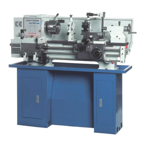
Metal Cutting Process – Turning Introduction This training guide is designed to give you 'handson' experience through which you can gain a good appreciation of this wellknown type of machine tool. In particular your attention will be directed towards its operational uses and parameters, the general layout of controls, accessories, associated tooling, and the maintenance factors related to lathes. In order that you can make the most use of the limited time available on lathes it is essential that you use every chance to consolidate what you observe. This type of work is largely selfmotivated and the drive and desire to find out must come from you. It takes a considerable time to become a skilled lathe operator and to possess all the skill of hand that goes with it. Therefore it is not expected that you will be manually skilled on completion of the module but you will have gained intellectually and without doubt, by practical involvement, some skill of hand will be achieved. Figure 1. Example of a Typical Centre Lathe Chester UK Craftsman Lathe ... -
Page 11: Centre Lathe
The term Centre Lathe is derived from the fact that in its operation the lathe holds a piece of material between two rigid supports called centres, or by some other device such as a chuck or faceplate which revolves about the centre line of the lathe. The lathe shown above is a typical example. This machine is usually used in a jobbing (one off) situation or for small batch work where it would be too expensive to specially 'tool up' for just a few items. The lathe on which you will work is a machine used to cut metal. The spindle carrying the work is rotated whilst a cutting tool, which is supported in a tool post, is made to travel in a certain direction depending on the form of surface required. If the tool moves parallel to the axis of the rotation of the work a cylindrical surface is produced as in Fig 2 (a), whilst if it moves at right angles to this axis it produces a flat surface as in Fig 2 (b). Figure 2a. Producing a Figure 2b. Producing a Flat Surface Cylindrical Surface The lathe can also be used for the purposes shown in Fig 2c, 2d, 2e and 2f. Figure 2c. Taper Turning Figure 2d. Parting Off / Under Cutting Figure 2e. Radius Turning Attachment Figure 2f. Drilling on a Lathe Chester UK Craftsman Lathe ... -
Page 12: Cutting Tools
(i.e. productive) way. The tools used in a lathe are various, some of which are shown in figure 3. The range of cutting tool types is extensive and a few examples only are shown in this handout. Nonetheless you should take every opportunity to look deeper into the types of tools available. Chester UK Craftsman Lathe ... -
Page 13: Basic Theory
. Figure 4. Basic Metal Cutting Theory Figure 4 shows a tool being moved against a fixed work piece. When the cut is in progress the chip presses heavily on the top face of the tool and continuous shearing takes place across the shear plane AB. Although the Figure shows a tool working in the horizontal plane with the work piece stationary, the same action takes place with the work piece revolving and the tool stationary. Chester UK Craftsman Lathe ... -
Page 14: Tool Angles
A compromise must therefore be made between adequate strength and good cutting action . Hard Steel / Medium Metal Being Cut Cast Iron Mild Steel Aluminium Brass Carbon Steel Top Rake Angle 0° 8° 14° 20° 40° Table 1. Typical value for top rake angle Clearance Angle Clearance angle is the angle between the flank or front face of the tool and a tangent to the work surface originating at the cutting edge. All cutting tools must have clearance to allow cutting to take place. Clearance should be kept to a minimum, as excessive clearance angle will not improve cutting efficiency and will merely weaken the tool. Typical value for front clearance angle is 6° in external turning. Chester UK Craftsman Lathe ... - Page 15 The trailing edge of the tool is ground backwards to give clearance and prevent rubbing and a good general guide is to grind the trailing edge at 90° to the cutting edge. Thus the Trail Angle or Relief Angle will depend upon the approach angle. A small nose radius on the tool improves the cutting and reduces tool wear. If a sharp point is used it gives poor finish and wears rapidly. Chester UK Craftsman Lathe ...
- Page 16 Characteristics of Tool Material For efficient cutting a tool must have the following properties : Hot Hardness This means the ability to retain its hardness at high temperatures. All cutting operations generate heat, which will affect the tools hardness and eventually its ability to cut. Strength and Resistance to Shock At the start of a cut the first bite of the tool into the work results in considerable shock loading on the tool. It must obviously be strong enough to withstand it. Low Coefficient of Friction The tool rubbing against the work piece and the chip rubbing on the top face of the tool produce heat, which must be kept to a minimum. Chester UK Craftsman Lathe ...
-
Page 17: Tool Material
High Speed Steel (H.S.S.) Steel, which has a hot hardness value of about 600° C, possesses good strength and shock resistant properties. It is commonly used for single point lathe cutting tools and multi point cutting tools such as drills, reamers and milling cutters. Cemented Carbides An extremely hard material made from tungsten powder. Carbide tools are usually used in the form of brazed or clamped tips. High cutting speeds may be used and materials difficult to cut with HSS may be readily machined using carbide tipped tool. Chester UK Craftsman Lathe ... -
Page 18: Tool Life
Tool Life As a general rule the relationship between the tool life and cutting speed is VTn = C where; V = cutting speed in m/min T = tool life in min C = a constant For highspeed steel tools the value of C ranges from 0.14 to 0.1 and for carbide tools the value would be . Chester UK Craftsman Lathe ... - Page 19 The type of chip produced depends on the material being machined and the cutting conditions at the time. These conditions include the type of tool used tool, rate of cutting condition of the machine and the use or absence of a cutting fluid . Continuous Chip This leaves the tool as a long ribbon and is common when cutting most ductile materials such as mild steel, copper and Aluminium. It is associated with good tool angles, correct speeds and feeds, and the use of cutting fluid. Figure 7. Continuous Chip Discontinuous Chip The chip leaves the tool as small segments of metal resulted from cutting brittle metals such as cast iron and cast brass with tools having small rake angles. There is nothing wrong with this type of chip in these circumstances. Figure 8. Discontinuous Chip Chester UK Craftsman Lathe ...
- Page 20 Continuous Chip with Builtup Edge This is a chip to be avoided and is caused by small particles from the work piece becoming welded to the tool face under high pressure and heat. The phenomenon results in a poor finish and damage to the tool. It can be minimised or prevented by using light cuts at higher speeds with an appropriate cutting lubricant . Figure 9. Continuous Chip with Buildup Edge Chip Breaker A chip breaker is used to break the continuous chip into sections so that the chips cannot tangle around the cutting tool. Grinding a groove on the tool face a few millimeters behind the cutting edge makes the simplest form of chip breaker. Chester UK Craftsman Lathe ...
-
Page 21: Cutting Speed / Feed
Feed The term `feed' is used to describe the distance the tool moves per revolution of the work piece and depends largely on the surface finish required. For roughing out a soft material a feed of up to 0.25 mm per revolution may be used. With tougher materials this should be reduced to a maximum of 0.10 mm/rev. Finishing requires a finer feed then what is recommended. Chester UK Craftsman Lathe ... -
Page 22: Cutting Fluid / Lubric
Mineral Oils They are used for heavier cutting operations because of their good lubricating properties and are commonly found in production machines where high rates of metal removal are employed. Mineral oils are very suitable for steels but should not be used on copper or its alloys since it has a corrosive effect. Vegetable Oils They are good lubricants but are of little used since they are liable to decompose and smell badly. Chester UK Craftsman Lathe ... -
Page 23: Screw Cutting
It is a slightly more difficult task than plain turning because it involves accurate setting up of the tool and exact setting of feed in relation to the work rotation. Once this is done however, and this you will be shown, the process of screw cutting becomes relatively simple. Fig 10 shows the arrangement in simplified form. Figure 10. Screw Cutting Setup There are many different forms of screw thread; Fig 11 shows the 'sections' of three most common types. More types and specifications of screw threads can be found in any Workshop Technology Hand Books and you must get used to finding such information and knowing how to apply it. Figure 11. Types of Screw Thread Chester UK Craftsman Lathe ... -
Page 24: Conclusion
In this respect the types of maintenance routine carried out, the design and accessibility of the maintenance system, and the lubricants used, are all factors that require your attention. Chester UK Craftsman Lathe ... -
Page 25: Parts
Parts Bed Assembly Chester UK Craftsman Lathe ... - Page 26 Chester UK Craftsman Lathe ...
-
Page 27: Headstock Assembly
Headstock Assembly Chester UK Craftsman Lathe ... - Page 28 Chester UK Craftsman Lathe ...
- Page 29 Chester UK Craftsman Lathe ...
- Page 30 Chester UK Craftsman Lathe ...
-
Page 31: Gearbox Assembly
Gearbox Assembly Chester UK Craftsman Lathe ... - Page 32 Chester UK Craftsman Lathe ...
- Page 33 Chester UK Craftsman Lathe ...
-
Page 34: Apron Assembly
Apron Assembly Chester UK Craftsman Lathe ... - Page 35 Chester UK Craftsman Lathe ...
- Page 36 Chester UK Craftsman Lathe ...
-
Page 37: Saddle Assembly
Saddle Assembly Chester UK Craftsman Lathe ... - Page 38 Chester UK Craftsman Lathe ...
-
Page 39: Tool Post Assembly
Tool Post Assembly Chester UK Craftsman Lathe ... - Page 40 Chester UK Craftsman Lathe ...
-
Page 41: Tailstock Assembly
Tailstock Assembly Chester UK Craftsman Lathe ... - Page 42 Chester UK Craftsman Lathe ...
-
Page 43: Control Rod Assembly
Control Rod Assembly Chester UK Craftsman Lathe ... - Page 44 Chester UK Craftsman Lathe ...
- Page 45 Headstock Cover Assembly Chester UK Craftsman Lathe ...
- Page 46 Chester UK Craftsman Lathe ...
-
Page 47: Electric Sys. Assembly
Electric System Assembly Chester UK Craftsman Lathe ... - Page 48 Chester UK Craftsman Lathe ...
-
Page 49: Follow Rest Assembly
Follow Rest Assembly Chester UK Craftsman Lathe ... - Page 50 Chester UK Craftsman Lathe ...
-
Page 51: Steady Rest Assembly
Steady Rest Assembly Chester UK Craftsman Lathe ... - Page 52 Chester UK Craftsman Lathe ...
Need help?
Do you have a question about the Craftsman and is the answer not in the manual?
Questions and answers
What extra changewheels are supplied with the machine